Cycle links
Principles
This chapter sets out the requirements for the design of cycle links, which may comprise:
- Mixed traffic streets
- Cycle tracks
- Cycle lanes.
Mixed traffic streets allow cycle users to occupy the same space as motor traffic. They offer well-connected routes for cycle users and freedom of movement within a network, but only provide safe conditions and an acceptable level of service for users when motor traffic volumes and speeds are low. The criteria for this are set out in Section 3.3.
Cycle tracks separate cycle users from motor traffic, providing a degree of protection and enhancing the attractiveness of cycling within that corridor. These may be adjacent to the road carriageway, or detached facilities that are not associated with an adjacent road carriageway.
Cycle lanes within the road carriageway offer less protection to users and provide a low level of service. For this reason, cycle lanes are not a preferred facility but may be considered in the limited situations described in Section 3.7.
Routes incorporating cycle links may require a combination of these facilities. A consistent provision is likely to result in a more attractive route but cycle routes should respond to the local context of the street to ensure they add to the character and place of the area. Regardless of the facilities used, cycle links should be as convenient and direct as possible to attract new users. Cycle links should form part of a cohesive cycle network plan (as set out in Chapter 2) and not be planned and designed in isolation.
It is vital that cycle links do not compromise safe and attractive facilities for pedestrians. Where width is required to form a cycle link within an existing corridor, the reallocation of space from the road carriageway is always preferable.
Likewise, it is vital that motor traffic links do not compromise safe and attractive facilities for cycling. Where existing space is allocated to motor traffic, there should not be a presumption that all this space must be retained for motor traffic.
This chapter sets out the design requirements for different cycle link types, and how they interact with motor traffic lanes, pedestrians, and on-street features including bus stops, parking and loading.
Types of cycle link
The types of cycle link available vary in terms of the level of separation they provide, both between cycle users and motor traffic and between cycle users and pedestrians.
These are described in the relevant sections of this chapter. Initial consideration of the factors that influence their suitability is outlined in Table 3.1.
|
Link Type |
Considerations |
|---|---|
|
Mixed traffic streets |
· Mixing with motor traffic within suitable conditions · Greatest freedom of movement for cycle users |
|
Detached or remote cycle tracks |
· Not adjacent to motor traffic, thus provide greatest protection · May provide separation from pedestrians · May not link to as many trip attractors as other options |
|
Cycle track at carriageway level (adjacent to carriageway) |
· Provides physical protection from motor traffic (which may include light segregation) · Provides separation from pedestrians |
|
Stepped cycle track (adjacent to carriageway) |
· Provides physical protection from motor traffic · Provides separation from pedestrians |
|
Cycle track at footway level (adjacent to carriageway) |
· Provides physical protection from motor traffic · May provide separation from pedestrians |
|
Cycle lanes (on carriageway) |
· No physical protection from motor traffic · Provides separation from pedestrians |
Provision of appropriate facilities
Motor traffic is the main deterrent to cycling for many people. A reduction in motor traffic volumes and speeds will therefore improve the attractiveness of the route for cycle users. Greater physical protection from motor traffic will also improve user safety where suitable conditions cannot be created for mixed use streets. The suitability and most appropriate degree of protection will be influenced by local conditions.
When identifying the type of cycle link to provide on a corridor, the following require consideration:
- The desired level of protection and interaction between cycle users and motor traffic
- The desired level of separation and interaction between cycle users and pedestrians
- The opportunity that the cycle link will offer to enhance the surrounding environment and ‘place’ context of the link.
Protection from motor traffic
Key issues relating to the protection of cycle users from motor traffic are:
- Traffic volume and speed – The degree of protection required from motor traffic is largely influenced by the volume and speed of motor traffic. Higher speeds and higher traffic volumes necessitate a greater degree of protection. See Table 3.2 for guidance (pcu relates to passenger car units).
- Junctions and accesses – The number, location and type of junctions and local accesses on the corridor are also key considerations when identifying the type of link to provide. Regular breaks and disruptions to the cycle link are not desirable. An appropriate facility will seek to provide a continuous route to cycle users.
- Cycle user connections – Although a cycle link will provide a direct and attractive end-to-end facility, the positions at which cycle users are expected to join and leave that facility to link their journey require consideration. Where cycle links do not accommodate desirable movements, alternative design options that facilitate these movements may be more appropriate.
|
Clause Number |
Description |
|---|---|
|
3.3.1 |
Facilities to protect cycle users from motor traffic should provide a high level of service. Table 3.2 provides an indication of the levels of service that can generally be achieved by various facility types, based only on adjacent motor traffic volumes and speeds. Note: Other factors such as link length, signal phasing and surrounding environment also influence the level of service being achieved. Note: While remote cycle tracks are unaffected by adjacent motor traffic, the level of service they provide in relation to directness, personal security and access to facilities has to also be considered. |
|
3.3.2 |
Where cycle users are separated from motor traffic, this should be provided by physical means. Note: Physical separation offers greater protection to cycle users and provides a more attractive facility, regardless of adjacent vehicular speed and traffic flow. |
|
3.3.3 |
Cycle lanes should only be considered where cycle tracks cannot reasonably be provided, and where the on-carriageway conditions meet the criteria set out in Table 3.2. Note: On lower speed roads, a mixed traffic street which enables cycling in the primary lane position will often be preferable to a cycle lane. Refer to Section 3.8 |
| Mototr traffic speed (85th percentile) | Two-way traffic flow (pcu per day) | Two-way traffic flow (pcu per hour) | Mixed traffic street | Detached or remote cycle track | Cycle track at carriageway level | Stepped or footway level cycle track | Light segregation | Cycle lane |
|---|---|---|---|---|---|---|---|---|
| 0 to 30 kph | 0 to 2000 | 0 to 200 | High | High | High | High | High | Medium |
| 0 to 30 kph | 2000 to 4000 | 200 to 400 | Medium | High | High | High | High | Medium |
| 0 to 30 kph | 4000+ | 400+ | Low | High | High | High | High | Medium |
| 30 to 50 kph | 0 to 1000 | 0 to 100 | High | High | High | High | High | Medium |
| 30 to 50 kph | 1000 to 2000 | 100 to 200 | Medium | High | High | High | High | Medium |
| 30 to 50 kph | 2000 to 4000 | 200 to 400 | Low | High | High | High | High | Medium |
| 30 to 50 kph | 4000+ | 400+ | Low | High | High | Medium | Medium | Low |
| 50 to 65 kph | 0 to 1000 | 0 to 100 | Medium | High | Medium | Medium | Medium | Medium |
| 50 to 65 kph | 1000 to 2000 | 100 to 200 | Low | High | Medium | Medium | Medium | Low |
| 50 to 65 kph | 2000+ | 200+ | Should not be used | High | Medium | Medium | Low | Low |
| 65 to 80 kph | 0 to 1000 | 0 to 100 | Low | High | Medium | Medium | Medium | Low |
| 65 to 80 kph | 1000+ | 100+ | Should not be used | High | Low | Low | Low | Should not be used |
| 85 to 95 kph | 0 to 1000 | 0 to 100 | Low | High | Low | Low | Low | Low |
| 85 to 95 kph | 1000+ | 100+ | Should not be used | High | Low | Low | Should not be used | Should not be used |
| 95 to 110 kph | All | All | Should not be used | High | Low | Low | Should not be used | Should not be used |
In addition to the motor traffic speed and volume thresholds presented in Table 3.2, the designer should also consider the following when identifying the most appropriate means of protection from motor traffic:
- How does the presence of kerbside activity such as loading, parking and bus stops increase the risk to cycle users, even where the speed and volume conditions are met?
- How does the composition of traffic increase risk e.g. bus or HGV movements?
- Does the frequency of vehicles lead to platooning that could increase risk for short periods e.g. on approach to ferry terminals?
- Where dedicated cycle links are required to accommodate most users, how can these be accommodated in the geometric and placemaking design of the street?
Interaction between cycle users and pedestrians
The needs of all users should be considered fully in the design of any part of the built environment. In keeping with the Sustainable Travel Hierarchy, appropriate space for people walking, wheeling and cycling should be given precedence over space for motorised modes, particularly private vehicles.
Shared pedestrian and cycle facilities in inappropriate situations compromise the safety and attractiveness of the route to all users and are a significant barrier to accessibility. Available width can be a constraint to the provision of cycling facilities but does not justify the introduction of an inappropriate facility.
| Clause Number | Description |
|---|---|
| 3.3.4 | Where the provision of a separated facility is deemed necessary but is constrained by available space, means to achieve the required space should be identified, or alternative means of separation explored. |
| 3.3.5 | For new developments there should be a specific presumption in favour of separating pedestrian, cycling and motor traffic movements in the built environment. |
| 3.3.6 | Within built up areas where a cycling facility is to be located adjacent to a road, there should be a specific presumption in favour of separating pedestrian and cycle movements. |
The provision of a separated facility can be achieved by the reallocation of space from the road carriageway in favour of those walking, wheeling and cycling. At a network planning level, it can also be achieved by providing a higher level of service for cycle users on alternative routes, helping to distribute users and reduce levels of interaction between them.
As set out in Chapter 2, at new developments there is a unique opportunity to develop high quality facilities for all users at the outset, and there should be no physical constraint preventing the separation of users that cannot be overcome by good design.
Within built up areas where a cycling facility is to be located adjacent to a road, shared use facilities should only be used as a means of delivering route continuity where all other options have been examined and documented in the Design Review. At crossings and other points of interaction, there will sometimes be a need for users to mix and this is set out in Chapter 4.
In other circumstances, designers should consider the likely frequency and nature of interactions between users, as well as the number and relative proportions of people walking, wheeling and cycling. Factors which may make shared use facilities appropriate in these circumstances include:
- Low user density and therefore low potential conflict. Table 3.3 and 3.4 indicate the level of interaction relative to user volumes. The wider the route, the less conflict will be felt for a given number of user interactions
- A very low number of active frontages alongside a route, making it less likely that users will cross over each other to access amenities
- Low speed differential between users, often established by a high degree of non-linear movement, a high place function or high degree of leisure or other slow speed movement which influences the behaviour of users
- Where separation might encourage a high speed differential between users or lead to excessively complex layouts that are confusing for users and are likely to result in users straying into each other’s space.
Table 3.3 indicates how frequently a pedestrian can expect to encounter cycle users for various cycle flows. Table 3.4 similarly indicates how frequently a cycle user can expect to encounter pedestrians for a range of pedestrian flows. The levels of interaction indicated are based on walking speeds of 5 kph and cycling speeds of 15 kph, and would increase with higher speeds.
Cycle user access to pedestrianised areas or streets with restricted motor vehicle access can improve the permeability of the cycle network and allow cycle users direct and safe access to end destinations.
Prohibition of cycling in these areas is unlikely to be desirable or effective, as it would restrict this direct and safe access, and may be ignored where better route options are not available to cycle users.
In many pedestrianised settings or at particular times of day, higher speed through-movements by cycle users may be inappropriate. The most effective approach to minimise through movements in pedestrianised areas is to ensure that the surrounding network offers better Level of Service route options. Designers should take a network-wide approach to attract cycle users away from pedestrianised settings rather than introducing ineffective prohibitions.
| Experience of pedestrian | Cycle flow (two-way 30 per hour | Cycle flow (two-way 50 per hour | Cycle flow (two-way 100 per hour | Cycle flow (two-way 150 per hour | Cycle flow (two-way 300 per hour |
|---|---|---|---|---|---|
| Meeting a cycle user in opposite direction | 3 mins | 1 min 48 s | 54 s | 36 s | 18 s |
| Being overtaken by a cycle user | 6 mins | 3 min 36 s | 1 min 48 s | 1 min 12 s | 36 s |
| Experience of cycle user | Pedestrian flow (two-way 30 per hour | Pedestrian flow (two-way 50 per hour | Pedestrian flow (two-way 100 per hour | Pedestrian flow (two-way 150 per hour | Pedestrian flow (two-way 300 per hour |
|---|---|---|---|---|---|
| Meeting a pedestrian in opposite direction | 1 min | 36 s | 18 s | 12 s | 6 s |
| Overtaking a pedestrian | 2 mins | 1 min 12 s | 1 min 48 s | 36s | 12 s |
Surrounding environment of the link
In many cases, the decision on the type of link will also be guided by the surrounding environment or placemaking context of the route.
Alongside the considerations of separating cycle traffic from motor traffic and pedestrians, the contribution of the cycle link to its surroundings and how this influences the selection of the link will be important.
For example, the conditions suitable for mixed traffic streets are most likely to be met where the street has a greater ‘place’ function than ‘movement’ function, as advocated in the Scottish Government’s ‘Designing Streets’ policy statement. These are streets where there is (or there is potential for) a greater balance of people wishing to dwell and spend time on the street over those wishing to simply pass through, as illustrated in Figure 3.1.

The choice to separate cycle users from pedestrians and motor traffic can influence the overall function and place quality of the street. The following requires careful consideration at the outset of cycle link choice, particularly if the place function of the area is high:
- How the choice of separation for the cycle link will impact or restrict the use of the surrounding space, both for movement and dwelling purposes. This will require a review of how people currently use the space and identification of potential impacts
- How physical separation and the choice of materials used will impact the visual amenity of the surrounding space. This will require discussion with local planning officers in advance of planning applications
- How to maximise opportunities for improvements to blue/green infrastructure or urban design within the link and alongside it.
Cycling infrastructure can have a positive impact on the surrounding environment of the link if it is considered within the holistic design of the street or place.
Designers of cycling infrastructure are expected to work collaboratively with landscape and urban designers to identify and build in these opportunities from the outset of design. This document deals primarily with the design requirements for cycling infrastructure itself, and designers are encouraged to seek guidance from the Scottish Government’s Place Standard Tool and Green Infrastructure Design and Placemaking guidance.
Geometric design requirements
It is essential that facilities are provided that meet appropriate geometric standards. This will ensure that they are comfortable, safe, attractive and suitable for users and their cycle vehicles.
The geometric criteria established in this section are based on the design vehicle defined in Chapter 2. The needs of other cycle vehicles also have to be considered by designers, particularly at critical locations such as crossings and junctions, where the standard criteria may not be sufficient for all individual user requirements. Guidance on these additional considerations is provided when describing relevant facilities for crossings and junctions in Chapter 4 and Chapter 5 respectively.
Requirements for link geometry and cross sectional width are provided here.
Link geometry (alignment)
Requirements for link geometry, relating to horizontal and vertical alignment and sight distance, are defined in this section for three categories of cycle link:
- Local access links, which will tend to serve shorter journeys, often in more constrained environments and with higher potential for interaction with pedestrians. These are likely to be on secondary routes on the cycle network. Their requirements are defined on the basis of a design speed of 20 kph.
- Commuter links, which will tend to serve longer journeys and interchange points in less constrained environments on primary or secondary routes. Their requirements are defined on the basis of a design speed of 30 kph.
- Higher speed links, which will tend to be fully separated, primary routes where cycle users are expected to build up greater speed. Their requirements are defined on the basis of a design speed of 40 kph.
Cycle link geometry is determined by these categories, but is not determined by the type of cycle link provided. For example, the minimum link geometry requirements for a cycle lane forming part of a commuter link will be the same as the minimum link geometry requirements for a detached cycle track forming part of a commuter link.
Where cycle links are adjacent to roads, the geometry of the road will largely influence the geometry of the cycle link. Notwithstanding this, the geometry values defined in this section apply to all cycle links, and any reductions below the desirable minimum values will be subject to assessment through the Design Review process set out in Chapter 2.
The category of cycle link should be established based on route purpose and local characteristics, prior to development of the geometric design.
In some circumstances the category of link may vary along a corridor to reflect local conditions and how the link is used within specific sections of the corridor.
|
Clause Number |
Description |
|---|---|
|
3.4.1 |
Link geometry should be in accordance with Table 3.5. |
|
3.4.2 |
Dynamic sight distance should be measured from an eye height range of 0.8 m to 2.2 m, to a target height range of 0.8 m to 2.2 m, as illustrated in Figure 3.2. Note: Dynamic sight distance is the advance distance a cycle user requires to see ahead, to make the task of riding feel safe and comfortable and to pass slower cycle users and pedestrians. It is defined by the distance that a cycle user will travel in eight seconds at design speed. |
|
3.4.3 |
Stopping sight distance should be measured from an eye height range of 0.8 m to 2.2 m to a target height range of 0 to 2.2 m, as illustrated in Figure 3.2. Note: Stopping sight distance represents the ability of a cycle user to see an obstruction on the route ahead, and stop where necessary. |

| Criteria | Local access link (20 kph design speed) | Commuter link (30 kph design speed) | High speed link (40 kph design speed) |
|---|---|---|---|
| Sight distance - Dynamic desirable minimum | 44 m | 67 m | 89 m |
| Sight distance - Stopping desirable minimum | 17 m | 31 m | 47 m |
| Horizontal radius - Desirable minimum | 14 m | 32 m | 57 m |
| Vertical crest curvature - Desirable minimum (K) | 6 | 6 | 6 |
| Vertical sag curvature - Desirable minimum (K) | 5 | 5 | 5 |
| Gradient - Desirable maximum | 3% | 3% | 3% |
New cycle links will often be constrained by existing topography. Although this may be unavoidable in some locations, providing cycle links on steep gradients will not provide the highest level of service for all users, and alternative routes should be considered where practical.
Level of Service Indicators – Gradient
In relation to Design Principle – Comfort
- High Level of Service: There are no sections of route steeper than 3% gradient
- Medium Level of Service: Some sections of route exceed 3% gradient due to local topography, but the route is designed to minimise the length of these sections
- Low Level of Service: Much of the route exceeds 3% gradient
Additional width is required for cycle links on gradients greater than 3% to allow for additional lateral movement (for uphill cycling) and speed (for downhill cycling), as set out in Table 3.7. One-way cycle links will generally be preferable in these situations to reduce cycle user conflict. Where designers have space to provide a wider facility in one direction over another, more width should be given to the downhill direction to accommodate additional speed.
Vertical curvature is defined by minimum K values, where a crest curve represents a negative change in gradient (e.g. over the top of a hill) and a sag curve represents a positive change in gradient (e.g. through the low point of a valley). The K value is the distance required to alter the gradient by +/-1%. Crest curves affect forward visibility and their values are therefore determined on that basis. Sag values generally do not affect visibility and are therefore based on comfort.
| Clause Number | Description |
|---|---|
| 3.4.4 | Where ramps are provided on cycle links to access bridges or underpasses or to overcome local constraints, the desirable maximum gradient is 5%. |
| 3.4.5 | Higher gradients may be applied to ramps intended to be used by cycle users but it is recommended that the length and rise of these ramps is limited as shown in Table 3.6, which is aligned to the recommendation of Roads for All: Good Practice Guide for Roads. |
Consideration may be given to dual provision ramps. These can provide landings between the rise of ramps on one side for those users who will benefit from these, and the separate provision of ramps without landings on the other side for those who may find this more comfortable.
Cross-sectional geometry
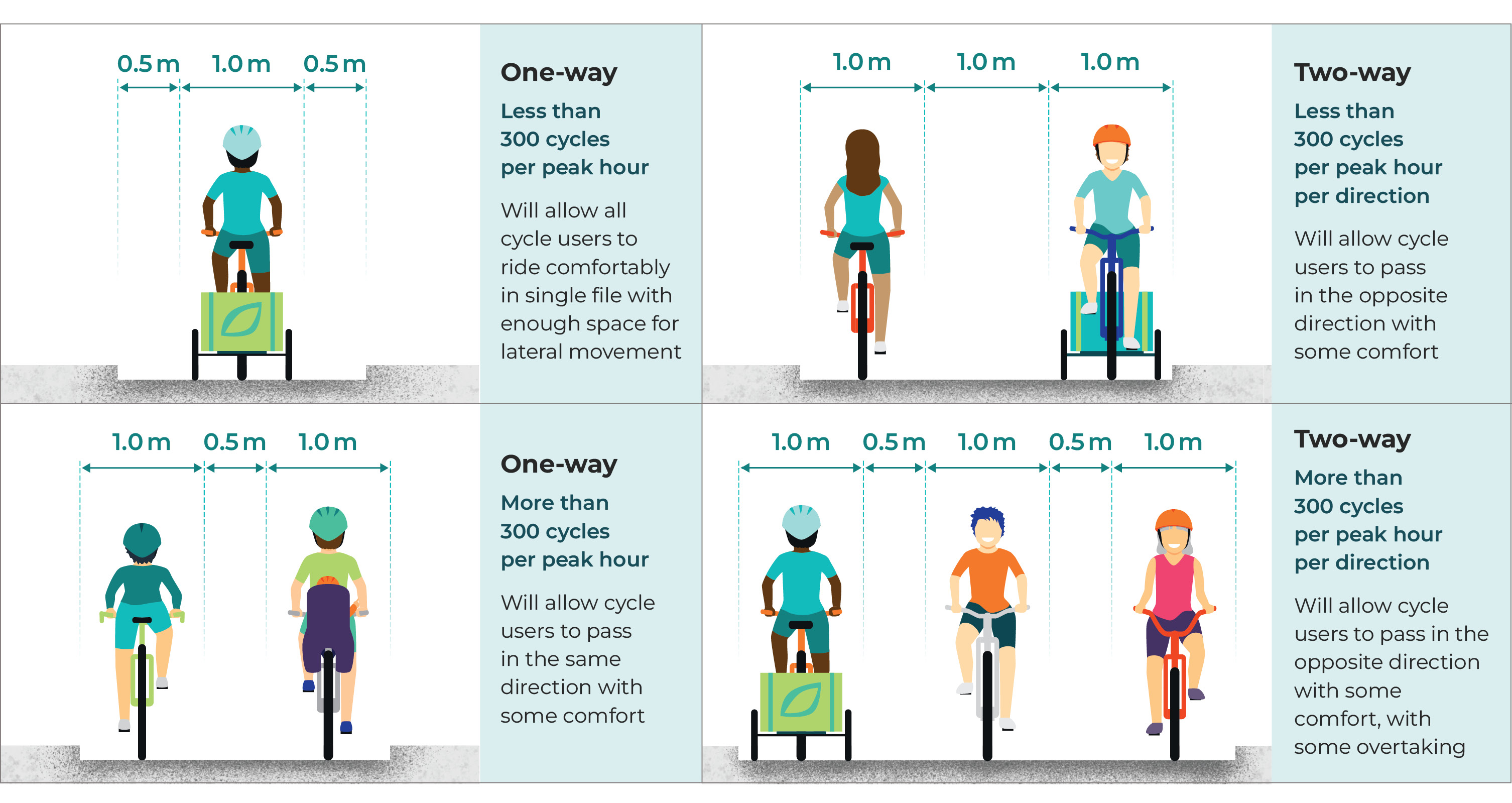
Cross sectional requirements will vary depending on the type of facility and the number of users expected. Figure 3.3 shows the widths needed to cycle comfortably alongside other users, illustrating the basis for the desirable width dimensions that are defined in this section.
| Facility | Benefits | Desirable width dimensions |
|---|---|---|
| One-way (less than 300 cycles per peak hour) | Will allow all cycle users to ride comfortably in single file with enough space for lateral movement | Cycling width of 1.0 m and 0.5 m buffer both sides |
| One-way (more than 300 cycles per peak hour) | Will allow cycle users to pass in the same direction with some comfort | Cycling width of 1.0 m per user (up to two users side by side) with 0.5 m buffer between |
| Two-way (less than 300 cycles per peak hour) | Will allow cycle users to pass in the opposite direction with some comfort | Cycling width of 1.0 m per user (up to two users side by side) with 1.0 m buffer between |
| Two-way (more than 300 cycles per peak hour) | Will allow cycle users to pass in the opposite direction with some comfort, with some overtaking | Cycling width of 1.0 m per user (up to three users side by side) with 0.5 m buffer between |
A 1.0 m dynamic width envelope will accommodate different types of cycle vehicle and allow sufficient space for the lateral movement needed for users to retain balance and momentum. A separation of 0.5 m will allow for comfortable overtaking and social cycling in the same direction, while a separation of 1.0 m will provide comfortable and safe passing in opposite directions.
Tables 3.7 and 3.8 show the dimensions that are required of the cycle track types described in the following sections. Facilities should be designed in accordance with the desirable minimum dimensions. Where desirable values cannot be achieved due to particular constraints, limited reductions are permissible, but the highest achievable standards should be maintained, subject to the Design Review process. Absolute minimum represents the scope of permissible reduction to this requirement. In balancing space when separating people walking and cycling, pedestrian space is considered first in accordance with the sustainable travel hierarchy.
It is vital that new cycle links and improvements to existing cycle links account for anticipated future volumes of cycle users and not just existing users. Links to guidance on assessing future demand are provided in Chapter 2.
| Cycle track types | Footway width | Separation | Cycle track width* (one-way, less than 300 cycles per hour peak) | Cycle track width* (one-way, more than 300 cycles per hour peak) | Cycle track width* (two-way, less than 300 cycles per hour peak, per direction) | Cycle track width* (two-way, more than 300 cycles per hour peak, per direction) | Buffer width |
|---|---|---|---|---|---|---|---|
| Remote cycle tracks separated from pedestrians (desirable minimum) | 2.0 m | Varies with facility | 2.0 m | 2.5 m | 3.0 m | 4.0 m | N.A. |
| Remote cycle tracks separated from pedestrians (absolute minimum) | 1.5 m | Varies with facility | 1.5 m | 2.0 m | 2.0 m | 3.0 m | N.A. |
| Remote cycle tracks shared with pedestrians (desirable minimum) | N.A. | N.A. | Not recommended | Not recommended | 4.0 m | Not recommended | N.A. |
| Remote cycle tracks shared with pedestrians (absolute minimum) | N.A. | N.A. | Not recommended | Not recommended | 2.5 m | Not recommended | N.A. |
| Cycle track adjacent to carriageway separated from pedestrians (desirable minimum) | 2.0 m | Varies with facility | 2.0 m | 2.5 m | 3.0 m | 4.0 m | Refer to Table 3.8 |
| Cycle track adjacent to carriageway separated from pedestrians (absolute minimum) | 1.5 m | Varies with facility | 1.5 m | 2.0 m | 2.0 m | 3.0 m | Refer to Table 3.8 |
| Cycle track adjacent to carriageway shared with pedestrians (desirable minimum) | N.A. | N.A. | Not recommended | Not recommended | 4.0 m | Not recommended | Refer to Table 3.8 |
| Cycle track adjacent to carriageway shared with pedestrians (absolute minimum) | N.A. | N.A. | Not recommended | Not recommended | 2.5 m | Not recommended | Refer to Table 3.8 |
| Speed limit | Minimum buffer width |
|---|---|
| 20 or 30 mph | 0.50 m |
| 40 mph | 1.00 m |
| 50 mph | 2.00 m (including any hard strip) |
| 60 mph | 2.50 m (including any hard strip) |
| 70 mph | 3.50 m (including any hard strip) |
Sufficient clearance is required to fixed objects and other features, such as street furniture, light segregation features and adjacent buildings and infrastructure. Greater proximity to fixed objects and features will reduce the effective width of the basic cross-sectional space for cycle users as they will position themselves to avoid these objects.
| Clause Number | Description |
|---|---|
| 3.4.6 | The clearance provided between the cycle track (or cycle lane) and fixed objects and features should be in accordance with Table 3.9. |
| Features | Minimum clearance |
|---|---|
| Vertical feature between 60 mm and 150 mm | 0.20 m |
| Vertical feature between 150 mm and 600 mm | 0.25 m |
| Vertical feature higher than 600 mm | 0.50 m |
| Ditch or slope | 0.50 m |
| Canal or other watercourse | 1.20 m |
| Equestrian route | 1.00 m |
Level of Service Indicators – Cross Section
In relation to Design Principle – Comfort
- High Level of Service: Desirable minimum widths are fully achieved
- Medium Level of Service: Some sections of the route fall below desirable minimum widths, or Most of the route falls below desirable minimum widths, but cycle user numbers are less than 50 per hour with limited scope for growth
- Low Level of Service: Most of the route falls below desirable minimum widths
In relation to Design Principle – Adaptability
- High Level of Service: Cross section of the route has the flexibility to expand, evolve or adapt to changing demands
- Medium Level of Service: Only some of the route has the flexibility to expand, evolve or adapt to changing demands
- Low Level of Service: No scope to amend cycling infrastructure once installed
| Clause Number | Description |
|---|---|
| 3.4.7 |
The maximum crossfall on a cycle link should be 2.5%. Note: The crossfall on all cycle links should be no more than is necessary for adequate drainage, to ensure that cycle users (and pedestrians where the link is shared) do not experience any discomfort when travelling at low speeds. Note: Camber rather than crossfall will be more comfortable for wheelchair users if the link is shared with these users. |
| 3.4.8 | Where existing on-carriageway crossfall exceeds 2.5%, the designer should assess the impact of this, modify the design accordingly and use the Design Review process to justify. Where necessary, alternative off-carriageway links should be developed. |
| 3.4.9 | Superelevation should not be specifically applied for cycle links. |
| 3.4.10 | Edge protection should be provided where there is less than 4.5 m clearance from the edge of the cycle link to steep drops, water hazards or other hazards that would otherwise lie in the path of an out-of-control cycle user. This would include cycle links on ramps to overbridges and underbridges. |
Detached or remote cycle tracks
Cycle tracks which are detached or entirely remote from any associated road carriageway offer the greatest level of protection from motor traffic and therefore have the potential to be very attractive to cycle users.
They are appropriate for use on long distance cycle links in rural areas, promoting recreational trips to various locations of interest, or equally to provide safer commuting between these areas. Detached or remote cycle tracks will usually be two-way, though associated one-way sections in each direction may be appropriate at constrained locations (such as through structures).
They also have potential to provide attractive facilities in more urban situations where they can be used to connect facilities between neighbourhoods, through parks and alongside canals. These cycle tracks often provide the best recreational and family-friendly routes in urban areas and can potentially act as wildlife corridors linking other greenspaces.
Detached or remote cycle tracks may be shared with pedestrians or may include separated pedestrian facilities. Where they are separated this may be by level (using a kerb) or at the same level by a paved or grass strip, or by kerb demarcation or delineation where space is limited. Grass or other planting in the separation strip can add ecological value to the cycle link and improve opportunities for sustainable drainage systems.
The interaction with pedestrians needs to be carefully considered, and the priority of pedestrian movement within the Sustainable Travel Hierarchy maintained.
Figures 3.4 to 3.6 illustrate a range of detached or remote cycle track layouts. Refer to Section 3.12 for cycle track construction options.


| Clause Number | Description |
|---|---|
| 3.5.1 | The desirable and absolute minimum widths for the cycle track and pedestrian facilities should be in accordance with Tables 3.7 and 3.8. |
| 3.5.2 | Where the cycle track is separated from pedestrians on the same level, this should be by means of a minimum 1.0 m strip that may be paved or grass. Where space is limited the width of separation may be reduced or be made by delineation. |
| 3.5.3 | Where the separation width is paved, it should incorporate a line of tactile paving between the cycle track and footway. Note: Care should be taken to ensure that raised demarcation kerbs or delineation strips do not create ponding e.g. by providing regular gaps in the line. The ability of blind and partially sighted users to detect the demarcation is an important consideration. A 20 mm profile is more detectable than a 12 mm profile. |
| 3.5.4 | Where grass (or other planting) is proposed within the separation area, the maintaining authority should be consulted. |
| 3.5.5 | For detached or remote cycle tracks separated by level, the separation width between the cycle track and footway is defined by the width of the kerb. |
| 3.5.6 | For detached or remote cycle tracks separated by level, the kerb between the cycle track and footway should be splayed and be 60 mm high. |
| 3.5.7 | Sections of one-way cycle track should not be shared with pedestrians. |
Steeper downhill gradients result in higher cycle speeds. On steeply graded separated tracks, cycle users should be routed to the outside of the sharpest bends where practical.
On steep, separated tracks, localised separation can be employed at bends in the same way. This avoids the need for separation along the full length but also offers protection for pedestrians.
Separation by verge has benefits on a steeply graded path, as it minimises the risk of cycle user encroachment onto the pedestrian space.
Detached or remote cycle tracks can form an important part of the cycling network but may be less effective at reaching key destinations and facilities on the route, particularly in urban environments.
Detached or remote cycle tracks also have potential to create actual or perceived personal security issues if not well designed. Care should be taken that sufficient width is provided, any vegetation is suitably offset from the cycle track and full visibility requirements are achieved to mitigate these risks. Lighting of remote cycle tracks is recommended to ensure a high level of service for users at night.
Level of Service Indicators – Personal Security
In relation to Design Principle – Attractiveness
- High Level of Service: The cycle link is well lit and overlooked. Full forward visibility is achieved and vegetation is regularly maintained
- Medium Level of Service: Some sections of the link are infrequently lit or overlooked. Vegetation or other obstacles create localised breaks in visibility
- Low Level of Service: Most of the link is infrequently lit or overlooked. Vegetation or other obstacles create regular breaks in visibility
Converting existing facilities to cycle tracks
Opportunities to provide remote cycle tracks may arise on existing or disused facilities.
Examples include:
- Conversion of a dismantled railway to a cycle track facility
- Conversion or provision of a cycle track facility on an existing canal tow path
- Conversion or provision of a cycle track facility on an existing bridlepath
- Conversion of an old single-track road that has been replaced by a new road.
In all cases, an assessment is required to ensure the suitability of the existing infrastructure for use, and to determine what construction works are required to develop the facility. The scope of this assessment will be influenced by the specific site, but issues to consider include:
- Interaction with pedestrian facilities and requirements
- Review of any actual or perceived safety risk resulting from remote routes
- Future infrastructure maintenance responsibility, including cycle track pavement, structures, signage, fencing and lighting
- Existing physical constraints to providing a compliant facility, such as existing overbridges or width restrictions
- Planning and consultation requirements with those authorities responsible for the existing infrastructure.
| Clause Number | Description |
|---|---|
| 3.5.8 | Geometric requirements for converted facilities should be in accordance with those generally defined for detached and remote cycle tracks. |
| 3.5.9 |
Clearance to watercourses and equestrian routes should be in accordance with Table 3.9. Note: Planning consents and agreements with landowners and operators are required when converting existing facilities to cycle tracks. Consultation with user groups may also be needed, including with the British Horse Society Scotland when developing a joint scheme involving an equestrian route. |
Access control
Barriers, gates and other forms of access control are often used on remote cycle tracks to prevent access by motor traffic or, in some cases, to control the speed of cycle users on approach to crossings or other points of interaction.
However, these access control measures may exclude some disabled people and others riding non-standard cycle vehicles from the cycle track. They may also require cycle users to dismount to negotiate the barrier, making the route less attractive and comfortable to cycle.
For these reasons, there should be a presumption against the use of access control measures unless there is a persistent and significant safety or personal security concern raised by unwanted access, including motor traffic or motorcycle access.
For the control of cycle user speed, it is preferable to adjust the horizontal alignment on approach to crossings or other points of interaction, and ensure that good forward visibility is provided to these points. This will allow cycle users to be fully aware of the interaction points and the need to adjust speed accordingly to give way to pedestrians or motor traffic if required.
Where access controls are provided (either through bollards on a cycle track or a gated access to restrict the movement of livestock), suitable spacing of 1.5 m should be provided to allow all types of cycle vehicle to pass unrestricted. These bypasses should be fully open to cycle users but may be controlled via self-closing gates if required by landowners.
Cattle grids can be difficult for cycle users to cross and should be avoided where cycle access is being designed.
Cycle tracks adjacent to carriageway
Cycle tracks are protected from the adjacent road carriageway by physical means. This distinguishes them from cycle lanes and provides a greater degree of comfort to cycle users, increasing their perceived and actual safety and the attractiveness of the route. They give cycle users greater confidence to use the road network.
On this basis, a physically protected cycle track is the preferred facility wherever a route is associated with an adjacent carriageway.
Cycle tracks of this type are most likely to lie between the road carriageway and pedestrian facilities. The following three sub-categories of cycle track adjacent to the carriageway are distinguished by their level, relative to the adjacent carriageway and pedestrian facility:
- Cycle track at carriageway level
- Stepped cycle track
- Cycle track at footway level
All of these can improve the attractiveness and quality of the street when designed as part of holistic street improvements, incorporating opportunities for planting, seating and activation of the spaces alongside the cycle track.
Cycle tracks at carriageway level and stepped cycle tracks maintain a level difference between cycle users and pedestrians. This layout is preferred, particularly in urban locations where pedestrian numbers are high, as it offers a greater degree of separation and therefore fewer potential interactions between pedestrians and cycle traffic.
A level difference is particularly significant in enabling blind and partially sighted users to be able to identify the cycle track and steer the pedestrian along its edge. Where no level difference is provided, it will be important to keep any building lines clear of street furniture to provide long cane users with an unobstructed route that can be easily navigated.
One-way cycle tracks are preferred to two-way cycle tracks when adjacent to the road carriageway, as they provide greater certainty to all road users of expected cycle movements and the interactions to be managed. Two-way cycle tracks can cause difficulties where kerbside activity is high, such as at bus stops, parking and loading areas. They are not suitable where only light segregation provides the protection from motor traffic. However two-way cycle tracks can be considered where they provide improved connections to the wider cycle network.
Where kerbs are employed, care is needed to ensure that surface water can run off from the cycle track and outfall at a suitable location, and avoid any ponding on the cycle track.
On roads that are one-way to general traffic, contra-flow or two-way cycle tracks can be installed to allow cycle users to travel in the opposite direction to the general traffic flow.
Cycle tracks can also be used to support speed reduction, by reducing the width available to general traffic. Where cycle tracks are formed within an existing road corridor, space should generally be reallocated from the road carriageway and not from pedestrian facilities.
Cycle track at carriageway level
A cycle track at carriageway level allows cycle users to cycle at the same level and often on the same surface as motor traffic, whilst providing physical protection between the two.
The level of protection from motor traffic, and therefore the degree of safety and attractiveness that is achieved, is influenced by the degree of physical protection provided. It is recommended that physical protection of a cycle track at carriageway level be provided by a kerbed reserve as shown in Figure 3.7, as this provides the greatest degree of protection.
Alternatively, protection may be provided by light segregation as shown in Figure 3.8. Light segregation can be achieved by features such as rubber kerbing, bollards and intermediate planters. These are quicker and cheaper to install than fully kerbed protection and thereby allow for trialling of measures in advance of permanent construction works.
Designers are required to consider the traffic conditions and level of use to determine whether light segregation offers sufficient protection to cycle users. It offers greater protection than painted cycle lanes and should be considered where a kerbed reserve cannot be reasonably provided.
Guidance on light segregation options is given in Table 3.10. Care should be taken that any form of light segregation is passively safe (i.e. minimises the severity of injury of anyone who may collide with it). All light segregation options are likely to result in a build-up of debris and detritus. This will have a maintenance implication and require enhanced or more frequent street cleaning which should be considered at the outset.
Where the cycle track is set at carriageway level, the adjacent pedestrian facility is separated from the cycle track by a level difference.
Refer to Section 3.12 for cycle track construction options.


Cycle tracks at carriageway level will often be preferred where a new cycle track is to be formed from space previously given to the road carriageway, and where it is not practical or desirable to form a stepped cycle track. They enable the existing carriageway crossfall to be maintained, which can be beneficial for drainage purposes. Where this is the case, regular gaps in the kerbed reserve are required to ensure continuity of surface water flow.
Cycle tracks at carriageway level are particularly appropriate where there are multiple side roads or minor accesses along the route, simplifying crossings without requiring level changes for the cycle user. The crossing of side roads and accesses is of importance to ensure the continuity of the cycle route in all scenarios. Design requirements for these are set out in Chapter 5.
| Clause Number | Description |
|---|---|
| 3.6.1 | The desirable and absolute minimum widths for the cycle track, pedestrian facilities and buffer should be in accordance with Tables 3.7 and 3.8. |
| 3.6.2 | The separation width between the cycle track and footway is defined by the width of the kerb. |
| 3.6.3 | The kerb between the cycle track and footway should be splayed and 60 mm high. |
| Option | Suitability | Advantages | Cons |
|---|---|---|---|
| Batons or Wands | Best suited to start/end of protected sections. | Height makes them highly visible to all users. Well recognised and understood. | Can be visually intrusive. |
| Armadillos or Zebras | Best suited to intermediate sections. | Robust low-level protection for cycle users. Minimal visual impact on streetscape. | Can be a trip hazard for pedestrians crossing informally. Low level makes them less visible to drivers and not favoured by motorcycle users. |
| Wand Orcas | Best suited to start/end of protected sections. | Height makes them highly visible to all users. Island element provides robust low-level barrier. | Can be visually intrusive. |
| Orcas | Best suited to intermediate sections. | Robust low-level protection for cycle users. Shallow gradient on cycle user side is more forgiving. Minimal visual impact on streetscape. | Can be a trip hazard for pedestrians crossing informally. Low level makes them less visible to drivers and not favoured by motorcycle users. |
| Rubber Kerbs | Best suited to intermediate sections. | Low visual impact. Quick and easy to install. | Low level makes them less visible to drivers and pedestrians, creating a potential trip hazard. |
| Landscaping Objects | Best suited to intermediate sections. | Robust low-level protection for cycle users. Visually appealing. | Potentially higher maintenance burden than other options. Easier to displace or damage. |
Stepped cycle tracks
Stepped cycle tracks provide protection between motor traffic, cycle traffic and pedestrians on three levels. This provides an additional degree of separation for cycle users from motor traffic, but also maintains the level difference between the cycle track and the footway, which is preferred by blind and partially sighted pedestrians.
Stepped cycle tracks are more space efficient than cycle tracks at carriageway level as they provide physical separation from the road carriageway without an additional kerbed reserve. However, they can be more complex to construct, and the absence of a kerbed reserve may entice motor traffic to use the stepped track for parking or loading activities.
For this reason, the inclusion of a raised kerb or light segregation may be provided within the buffer between the cycle track and the carriageway. This provides additional protection for cycle users and an additional deterrent to motor traffic, while ensuring that the necessary clearance width is provided. Figures 3.9 and 3.10 illustrate a stepped cycle track without and with light segregation (a raised kerb may be provided as an alternative to light segregation). Guidance on light segregation options is given in Table 3.10.
Refer to Section 3.12 for cycle track construction options.
Consistent cycle link design is vital to ensure the safety and attractiveness of a route. If it is not possible to provide a consistent stepped cycle track for suitable lengths of the route due to drainage, access or other requirements, then alternative link types will be more appropriate.


Stepped cycle tracks on existing road corridors should generally be formed through the reallocation of road space rather than taking space from the adjacent footway.
Where there is a demand for pedestrian crossing of the cycle track and adjacent road, the stepped cycle track should transition to a cycle track at carriageway level (or footway level if required) to provide a suitable crossing point for pedestrians.
Stepped cycle tracks often require additional drainage infrastructure, can be more complex to construct to achieve desired levels and may not be practical when retrofitting cycle tracks within constrained corridors. Drainage requirements will dictate the direction of crossfall, either to the roadside kerb or footway kerb.
Careful consideration of future cycle user volumes is needed to ensure adequate width is provided for overtaking, which can be less comfortable for users on stepped cycle tracks.
| Clause Number | Description |
|---|---|
| 3.6.4 | The desirable and absolute minimum widths for the cycle track, pedestrian facilities and buffer should be in accordance with Tables 3.7 and 3.8. |
| 3.6.5 | The separation width between the cycle track and footway is defined by the width of the kerb. |
| 3.6.6 | The kerb between the cycle track and footway should be splayed and of 60 mm height. |
| 3.6.7 |
Two-way stepped cycle tracks should not be provided. Note: Two-way stepped cycle tracks are likely to place cycle users adjacent to motor traffic moving in the opposite direction. Greater physical protection between cycle users and motor traffic is preferred in this case. |
Cycle track at footway level
It is desirable to separate pedestrians and cycle users by level, but this will not always be practical or achievable. Cycle tracks at footway level are usually less desirable but may be considered where:
- The available space allows for sufficient separation between pedestrians, cycle users and motor traffic as shown in Figure 3.11 and can be integrated into a holistically designed street
- The cycle track joins a detached cycle track at the same level
- There is a need for regular crossing of the cycle track by people with prams or in wheelchairs.
Separation between the cycle track and the pedestrian space minimises the potential for pedestrian and cycle interaction. Where space allows, this may be achieved by a paved or grass strip, or by kerb demarcation or delineation where space is limited. Grass or other planting in the separation strip can add ecological and placemaking value to the cycle link and improve opportunities for sustainable drainage systems.
In circumstances where there is less pedestrian activity, and therefore less likelihood of potential interactions between pedestrians and cycle users, it may be suitable not to separate users, as shown in Figure 3.12. Refer to Section 3.3 for guidance on when low levels of interactions between pedestrians and cycle users may allow mixed use as an alternative to separated facilities.
This arrangement will often be suitable in rural situations where pedestrian and cycle user levels are low. In rural areas the kerb between the edge of the road carriageway and the cycle track is not a requirement. In such cases the road speed will often be relatively high, and therefore a wider buffer is required in accordance with Table 3.8.
There should be a presumption against shared footways and cycle tracks alongside urban streets.
Refer to Section 3.12 for cycle track construction options.


| Clause Number | Description |
|---|---|
| 3.6.8 |
The desirable and absolute minimum widths for the cycle track, pedestrian facilities and buffer should be in accordance with Tables 3.7 and 3.8. Note: On very quiet rural routes a reasonable level of service may be achieved with an absolute minimum width on this type of facility. |
| 3.6.9 | Where the cycle track is separated from pedestrians on the same level, this should be by means of a minimum 1.0 m strip that may be paved or grass. Where space is limited the width of separation may be reduced or be made by demarcation kerb or delineation. |
| 3.6.10 |
Where the separation width is paved, it should incorporate a line of tactile paving between the cycle track and footway. Note: Care should be taken to ensure that raised demarcation kerbs or delineation strips do not create ponding e.g. by providing regular gaps in the line. The ability of blind and partially sighted users to detect the demarcation is an important consideration. A 20 mm profile is more detectable than a 12 mm profile. |
| 3.6.11 | Where grass (or other planting) is proposed within the separation area, the maintaining authority should be consulted. |
| 3.6.12 | Cycle tracks shared with pedestrians should be two-way. |
Cycle lanes
Cycle lanes allocate and define the available space for cycle users within a carriageway. They are delineated within the carriageway only by road markings.
Physically protected cycle tracks will provide a higher level of service than cycle lanes, due to the greater level of protection and the resulting level of safety and attractiveness of the facility for its users. Therefore, cycle lanes should only be considered where cycle tracks cannot reasonably be provided, and where the conditions on the adjacent carriageway are deemed to apply a low level of risk to cycle users (see Section 3.3).
Within limited circumstances, cycle lanes may provide some benefits to some users when compared to the absence of any facility. For those users, cycle lanes can reduce delay by providing a passing opportunity where traffic is queued. Limited sections of cycle lane may also be required to pass features such as side road junctions, or to provide cycle route continuity in very constrained situations.
Cycle lanes can increase drivers’ awareness of cycle users but they also encourage cycle users to take up a secondary position in the road carriageway (refer to Figure 3.14 for secondary position), which can result in drivers passing too closely. In most circumstances, it will be far better to provide a protected cycle track, or to create suitable mixed traffic street conditions where the cycle user is enabled to take up the primary position.
Where used, careful consideration of cycle lanes within the overall network is needed to ensure that less confident cycle users are not suddenly ‘exposed’ to sections of cycle lane, having been more comfortable in protected cycle tracks earlier in their journey.
| Clause Number | Description |
|---|---|
| 3.7.1 | The desirable minimum width of a cycle lane should be 2.0 m. |
| 3.7.2 |
The absolute minimum width of a cycle lane should be 1.5 m. Note: A narrow cycle lane can encourage close overtaking by motor traffic. |
| 3.7.3 | Where gullies are present on the cycle lane, they should be provided with a tighter mesh covering that is suitable for cycle wheels to cross, or the width of the cycle lane should be increased by the width of the gully. |
| 3.7.4 | Parking should be tightly controlled and enforced to ensure no motor vehicles stop or wait within the cycle lane. |
With-flow cycle lanes
Cycle lanes can be provided on two-way roads, in which case they run immediately adjacent to the carriageway lane running in the same direction.
Mandatory cycle lanes define an area of the carriageway that is reserved for cycle users and which other vehicles must not encroach upon within its hours of operation. Regulations relating to mandatory cycle lanes are defined in Schedule 9 of TSRGD.
Advisory cycle lanes are primarily used to warn motor vehicle drivers of the presence of cycle users and to encourage them to provide suitable space. However, it is permissible for motor traffic to drive within an advisory cycle lane, or to stop within the lane subject to parking and loading restrictions on the street. Advisory lanes therefore offer less benefit to cycle users.
|
Clause Number |
Description |
|---|---|
|
3.7.5 |
Cycle lanes on two-way roads should be with-flow i.e. the direction of the cycle flow should be the same as that of the adjacent traffic lane. |
|
3.7.6 |
With-flow cycle lanes should be mandatory, entirely reserved for cycle use and legally enforceable, subject to permitted exceptions. Note: Light segregation or kerbed protected cycle tracks will provide a higher level of service for most situations where a cycle lane is being considered. |
|
3.7.7 |
In the following permitted exceptions, with-flow cycle lanes may be advisory: · Where the remaining width of an adjacent motor traffic lane is less than 3.25 metres · Where the cycle lane is adjacent to areas of parking and loading where motor vehicles may need to cross the lane (see Section 3.11). Note: In these circumstances, the measures described in Section 3.8 for mixed traffic streets should be considered first to support low traffic speeds. |
|
3.7.8 |
Sections of mandatory with-flow cycle lanes may transition to advisory cycle lane over limited lengths as they cross junctions and accesses. |
Contra-flow cycle lanes
To improve the permeability of the cycle network, cycle users may be exempt from road closures, one-way streets and banned turns where new traffic management proposals are being considered. Contra-flow cycle lanes can be used in mixed traffic streets to provide a visible space for cycle users to travel in the opposite direction from motor traffic.
In general, there should be a presumption when planning cycle networks that all streets will be two-way for cycle users. On streets with one-way restrictions for motor traffic, a contra-flow (or two-way) protected cycle track will offer the most safe and attractive facility to cycle users. Alternatively, where traffic conditions permit, a contra-flow cycle lane may be considered as set out in Figure 3.13.
Where traffic conditions allow for mixed traffic streets, consideration can be given to two-way cycling with only minimal delineation of the cycle lane by using advisory lanes.
This can only be pursued where both cycle user visibility requirements and vehicle driver awareness of cycle movements in the opposite direction can be achieved. Narrow streets, parked cars, street furniture and other objects will limit this visibility and awareness, particularly of recumbent and hand cycle users.
| Clause Number | Description |
|---|---|
| 3.7.9 | Contra-flow cycle lanes should usually be mandatory, entirely reserved for cycle use, and must exempt cycle users from the street's one-way regulation. |
| 3.7.10 | The exemption to the one-way restriction should be indicated by signs advising of the exemption. |
| 3.7.11 | Sections of mandatory contra-flow cycle lane may transition to advisory cycle lane over limited lengths as they approach junctions and accesses. |
| 3.7.12 | The width of the opposing traffic lane should be between 3.0 m and 3.2 m to allow comfortable cycling in the same direction whilst not requiring encroachment to the contra-flow lane. |
| 3.7.13 |
Light segregation or kerb protection may be added to contra-flow cycle lanes where there is a risk of vehicle encroachment. Note: Two-way cycling can be permitted on one-way streets without contra-flow cycle lanes where space and visibility for passing is available. When no delineation is provided cycle symbols can be used to remind drivers of the presence of oncoming cycles. |

Shared bus and cycle lanes
Cycle users can use shared bus and cycle lanes unless restricted from doing so by a traffic regulation order. Allowing cycle users to share bus lanes will provide the benefits of improved route choice on the cycle network, though these benefits are limited to experienced and confident cycle users only.
For these reasons, cycle networks should offer an alternative cycle route to a shared bus and cycle lane and new cycle facilities should not be planned to share space with buses.
| Clause Number | Description |
|---|---|
| 3.7.14 |
Shared bus and cycle lanes should be a minimum of 4.0 m wide. A width of 4.6 m is more desirable and provides a higher level of comfort for cycle user. A cycle lane may be marked within this space. Note: Lane widths of 4.6 m will allow buses to comfortably overtake cycle users within the lane. |
| 3.7.15 | Where this cannot be achieved, shared bus and cycle lanes may be 3.2 m wide. |
| 3.7.16 |
Lane widths between 3.2 m and 4.0 m should be avoided. Note: Lane widths between 3.2 m and 4.0 m have potential to encourage unsafe overtaking of cycle users within the lane. |
| 3.7.17 | Cycle users should not be encouraged to use offside bus lanes (lanes not immediately adjacent to the kerbside) due to the presence of traffic on both sides. |
These requirements apply equally to contra-flow bus lanes. Care should be taken when amending existing shared contra-flow bus and cycle lanes to ensure that narrow lanes do not encourage buses to leave the bus lane to pass cycle users, thus increasing the risk of collision with oncoming traffic.
Mixed traffic streets
Mixed traffic streets allow cycle traffic to mix with motor traffic and bring the following potential benefits:
- Freedom of movement for cycle users for access and egress
- Space efficiency and flexibility of the street’s function and use
- Increased driver awareness of cycle users, particularly where the design enables more cycle users to use the street, supporting the control of traffic speed
- Easier and less expensive to provide and maintain.
- Opportunity to improve pedestrian experience and street environment.
These conditions and benefits are likely to be easier to establish where the street has a greater ‘place’ function than ‘movement’ function, such as on quieter residential streets.
Designing for cycle traffic to occupy the same space as motor traffic requires traffic volumes and speeds to be low, as set out in Section 3.3.
When considering the suitability of a mixed traffic street, and developing proposals, designers can:
- Identify streets that meet the traffic volume and speed thresholds required for mixed traffic, and include these streets when promoting joined-up cycle networks
- Identify the conditions that need to be achieved on streets where mixed traffic would be beneficial for cycle networks and put measures in place to achieve these conditions (i.e. reduce traffic volume and/or speed).
Creating the right conditions will allow the expansion of the cycle network through ‘quiet routes’ or ‘cycle streets’ and complement protected cycle links.
Limiting the speed differential between cycle users and motor traffic is critical to cycle users’ safety and comfort and to drivers’ appreciation of cycle users’ space. As cycle users will usually travel between 10 and 15 mph, maintaining traffic speed at or below 20 mph through design is an important aspect of road safety.
Low speed conditions should be self-enforcing through design that does not encourage higher motor vehicle speed. Low speed conditions can be supplemented by mandatory 20 mph speed limits.
Whilst cycle traffic may also mix with motor traffic where there is a greater movement function than place function of the road or street (such as on low-trafficked rural roads), this is likely to introduce a greater risk to cycle user comfort and safety, making mixed use attractive for only a limited number of cycle users. Cycle tracks that are detached or remote from the carriageway are therefore preferable in most rural situations.
| Clause Number | Description |
|---|---|
| 3.8.1 | Where the street conditions for cycle users to mix with motor traffic cannot be met, a protected cycle link should be provided. |
Cycle riding positions with mixed traffic
When mixing with motor traffic, cycle users will be more visible to drivers when adopting the primary riding position (the same position as a vehicle will adopt in a lane, to avoid being overtaken).
Maintaining a consistent riding position between junctions is a key requirement for comfortable cycling. Cycle users are only likely to adopt the secondary riding position (positioned closer to the kerb than other vehicles) if they can maintain this position consistently and are not required to weave between positions. A clearance of approximately 1.5 m is required between cycle users and motor traffic to allow safe and comfortable overtaking.
The width of traffic lanes on mixed traffic streets is therefore of critical importance. Many streets in Scotland have been developed to provide a 7.3 m road carriageway, in line with DMRB geometric requirements. This creates typical lane widths of around 3.65 m that are too wide for a cycle user to safely take up a primary position, but not wide enough to allow motor traffic to safely overtake cycle users without straddling lanes.
| Clause Number | Description |
|---|---|
| 3.8.2 | Where streets are designed for cycle users to mix with motor traffic, traffic lane widths should be designed to be between 2.8 m and 3.2 m to allow cycle users to safely adopt the primary riding position. |
| 3.8.3 | Where cycle users are expected to adopt the secondary riding position on a continual basis, the street design should formalise this arrangement by provision of a protected cycle link. |
Allowing cycle users to safely adopt the primary position requires careful street design to maintain the necessary traffic speed thresholds. This is particularly important if buses or heavy goods vehicles are expected to use the street.

Measures to reduce traffic volume
Controlling traffic volumes on mixed traffic streets should be planned at network level, as set out in Chapter 2.
These include options for filtered permeability, which restricts the route choices available to motor traffic within a local network, whilst retaining route choice and direct access for walking and cycling. This can be achieved by modal filters (preventing vehicle access by bollards but allowing cycle movements) or one-way plugs (allowing vehicle movements in one direction only). Figure 3.15 provides some filtered permeability options.
| Clause Number | Description |
|---|---|
| 3.8.4 | One-way plug options should not restrict cycling movements. |
| 3.8.5 | Designers should identify which permeability option is most likely to reduce through-traffic in local areas. |
| 3.8.6 | Additional design features such as deflection islands may be applied to supplement the permeability option. |
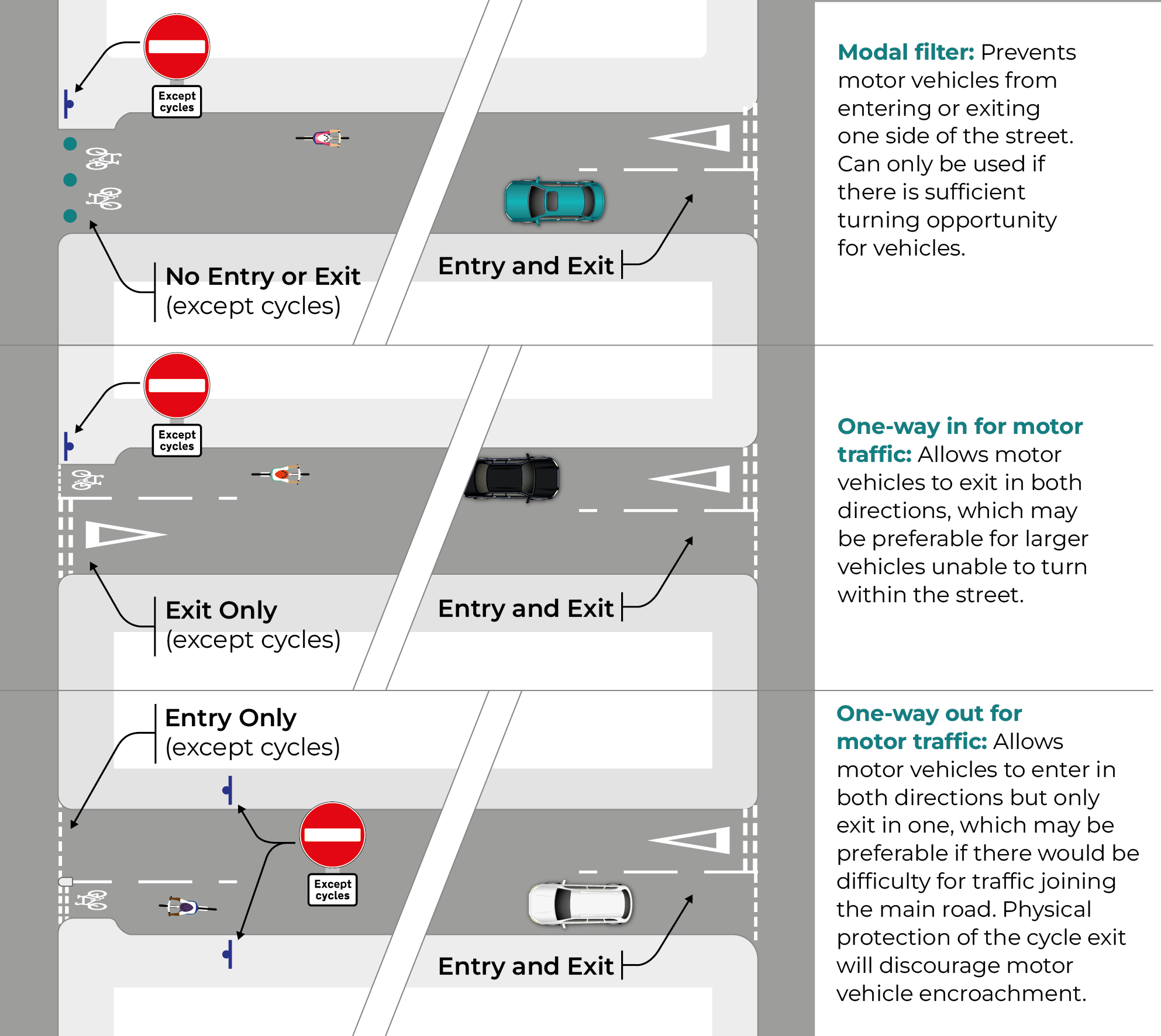
Filtered permeability options:
- Modal filter: prevents motor vehicles from entering or exiting one side of the street. It can only be used if there is sufficient turning opportunity for vehicles.
- One-way in for motor traffic: allows motor vehicles to exit in both directions, which may be preferable for larger vehicles unable to turn within the street.
- One-way out for motor traffic: allows motor vehicles to enter in both directions but only exit in one, which may be preferable if there would be difficulty for traffic joining the main road.
Figure 3.15: Filtered permeability options
Measures to reduce traffic speed
Once the traffic conditions across the network have been established, the design of individual streets will support the desired outcome of sustained, low traffic speeds to maintain cycle friendly conditions on streets intended for on-carriageway cycling.
It is important that the low speed environment of the street is self-explanatory and self- enforcing. This will ensure that these conditions are maintained as the use of the street varies throughout the day.
Designing Streets sets out Scottish Government policy for street design, including guidance on how the speed of traffic should be controlled:
Designers should aim to create streets that control vehicle speeds naturally by well-crafted design from the outset rather than through unsympathetic traffic-calming measures added at the end of the design process
Evidence from traffic calming schemes suggests that speed controlling features are needed at intervals of around 60-80 m in order to achieve speeds of 20 mph or less. Straight and uninterrupted links should therefore be limited to this range to help ensure that the arrangement has a natural traffic-calming effect.
Designing Streets, 2010
Creating more comfortable conditions for on-carriageway cycling can be achieved through holistic street design, by providing visual and psychological calming techniques which will contribute to the wider placemaking and wellbeing outcomes of good street design.
This is preferable to the retro-fitting of isolated measures that will slow the speed of traffic on existing streets, but isolated measures may still have the desired effect of slowing traffic that will make on-carriageway cycling more comfortable. In such cases, isolated measures should always be integrated to the surrounding environment and place context of the street.
Many streets that create suitable conditions for cycling will also be used by refuse vehicles, delivery vehicles and other large vehicles and the needs of these vehicles must be included in street design, whilst controlling their speed. With small corner radii, large vehicles may need to use the full carriageway width to turn.
The measures presented in Cycling by Design to create these conditions can be supplemented by planting and other forms of blue / green infrastructure to provide additional ecological value and resilience to local flooding, in line with Scottish Government policy on climate change.
Application of measures to mixed use streets
Guidance is given on the following pages on the application of measures to control motor traffic speeds on the following types of mixed use street:
- Quiet residential streets
- Cycle streets
- Mixed use streets with wider existing carriageway
Quiet Residential Streets
On most quiet residential streets, it will be possible to control traffic volumes (through the use of low traffic neighbourhoods set out in Chapter 2) and traffic speeds (through the use of the measures set out below) to provide suitable conditions for mixed traffic.

The following typical street design measures will assist in reducing traffic speeds:
- Tight corner radii at junctions. These are recommended to be 4.0 m or less to reduce motor traffic turning speed when entering the street. Large vehicles may need to use the full carriageway width to turn.
- Continuous footways or raised tables at side street entries. Continuous footways provide additional benefit to pedestrians and cycle users on the main street, and guidance is given on their application in Chapter 5. Where they are not desirable, raised tables should be considered with ramps at a maximum gradient of 1:10. On bus routes, the maximum gradient of ramps will be 1:15, subject to consultation with local bus operators.
- Raised tables at junctions. Ramps on approach to raised tables should commence a minimum of 3.0 m in advance of the junction corner to provide step-free crossings for pedestrians.
In addition, the following street design measures can assist in creating a visual narrowing of the space dedicated to motor traffic, making vehicle drivers more aware of the potential interaction with other users and more likely to control their speed:
- Centre line removal. The absence of centre line markings will make drivers more aware of potential conflict, reduce speed and encourage drivers to overtake a cycle user with greater clearance, and will be preferable in most cases to edge or median strips. Centre line markings are required where they convey a warning about a hazard, such as the presence of an island or approaching junction.
- Visual narrowing via edge strips. Edge strips should be a minimum of 0.5 m wide, of contrasting colour or material to the carriageway to emphasise its visual narrowing effect. Edge strips should be flush with the carriageway to allow overrun where necessary. Contrasting colour or material for edge strips will have a greater impact on driver behaviour but maintenance implications may be a restricting factor.
- Footway build outs. Build outs support the visual narrowing of the carriageway and improve crossing opportunities and the visibility of pedestrians.
Cycle streets
Where cycle volumes are expected to be high on mixed use streets, consideration should be given to the creation of a ‘cycle street’. The purpose of a cycle street is to convey a sense of cycle user priority within a mixed street environment and for motor traffic to be treated as ‘guests’ within this environment.
Cycle streets will be suitable where the following conditions can be met:
- Cycle traffic volumes are expected to be higher than motor traffic volumes
- The street forms a key part of the wider cycle network and is expected to maintain high cycle volumes over time
- The street does not form a through-route for motor traffic and is expected to maintain low motor traffic volumes and speeds over time
These streets will apply many of the same measures aimed at controlling motor traffic speeds on quiet residential streets but will be visually distinctive from other streets to convey their intended purpose. Typically, this will involve a coloured surface across the length of the cycle street (see Section 3.12) and priority given to the cycle street at junctions.

Mixed traffic streets with wider existing carriageway
On mixed traffic streets with a wider existing road carriageway, the following design measures should be considered in addition to those described above to support the visual narrowing of the carriageway and improve opportunities for safe cycling and pedestrian movements.
- Visual narrowing via median strips. Median strips should be a minimum of 1.0 m wide and of contrasting colour or material to the carriageway to emphasise its visual narrowing effect. Median strips should be flush with the carriageway to allow overrun where necessary. The remaining carriageway lane width should be between 2.8 m and 3.2 m.
- Informal crossing refuges using low level street furniture can define less formal crossing locations or to trial new crossing locations. Street furniture should include reflective strips to ensure suitable visibility at all times of day and night.

Finally, the following isolated horizontal deflection measures can support vehicle speed reduction on local roads but are less sympathetic to holistic street design and the placemaking outcomes desired by Scottish Government policy.
- Cycle bypass at pinch-points. Cycle users may be given priority by narrowing the width given to motor traffic and allowing cycle users to bypass.
- Where other measures are not considered sufficient to reduce vehicle speed on streets with significant forward visibility, lane deflection chicanes may be used in conjunction with give way markings.

| Clause Number | Description |
|---|---|
| 3.8.7 | At pinch-points and lane deflections, motor traffic should have an available width of at least 3.0 m and the cycle bypass lanes at least 1.5 m. |
| 3.8.8 | At pinch-points and lane deflections, island widths should allow 0.5 m clearance to bollards or other street furniture. |
| 3.8.9 | At lane deflection chicanes, stagger length L should be between 9.0 m and 13.0 m to maintain vehicle speeds below 20 mph, but should be confirmed by swept path analysis for longer vehicles. |
| 3.8.10 | Lane deflection at pinch-points should only be applied where the 85th percentile approach speed of traffic is 50 kph or lower and there are no obstacles to visibility of the gateway by oncoming vehicle drivers. |
| 3.8.11 | Parking should be restricted at pinch-points. |
Each of these design measures may be used in isolation or combination to meet the specific requirements of the street. Designers should consider the full length of the street when applying measures to control traffic volume and apply these measures as part of a holistic design approach. This should include public realm and landscaping improvements that can add to the overall sense of place on the street and contribute to low motor traffic speeds.
Where streets cannot be designed holistically but traffic speed needs to be controlled, the designer may apply isolated speed control measures to make on-carriageway cycling more comfortable but should seek to integrate these measures within the wider street design approach.
Combined with other measures, a change in surface material may be used to reinforce the expected change in driving behaviour approaching key entries, junctions or facilities such as schools.
Vertical traffic calming measures are often unsuitable within the street context due to their limited effect in reducing motor vehicle speed and the problems they pose to non-standard cycles and trailers. Where speed humps are to be incorporated into a wider street design, these should be sinusoidal in profile rather than flat-topped to reduce the impact on cycle user comfort. Where speed cushions are to be incorporated into a wider street design, they should be carefully positioned to allow cycle users to continue on a line that maintains the primary riding position and avoids the cushions.
Constrained sections of road
In many settlements, the limited width between building lines will make it impractical to provide a protected cycle link alongside a single road carriageway. This makes it even more important to control traffic conditions to allow cycle users to safely share the carriageway within these settlements, with suitable gateway features to indicate this change.
Lane deflections at pinch-points can be effective in slowing the speed of traffic entering the constrained section of road, with entering traffic giving way to oncoming traffic. Entrance gateways to rural settlements may be used in combination with lane deflections to further control the speed of traffic.
Contrasting surface materials, removal of the centre line and provision of cycle symbol road markings can also be considered through the constrained section to highlight the mixed traffic nature of that section, as shown in Figure 3.20.
| Clause Number | Description |
|---|---|
| 3.8.12 |
Cycle users should only be mixed with motor traffic in constrained sections of road where a high level of service can be achieved, as set out in Table 3.2. Note: Protected cycle tracks will otherwise be preferable if roadspace can be reallocated to provide these. |

Passing places
On low-trafficked single-track roads experiencing an increasing number of cycle users, additional passing places and cycle warning signs to TSRGD Diagram 950 can be used to increase drivers’ awareness of cycle users.
Where cycle users are required to share single-track roads with motor traffic, additional passing places on inclines and where forward visibility is most limited will allow cycle users to slow down and allow vehicles to pass without coming to a complete stop. The length of passing places will depend on actual traffic speeds and forward visibility at each location.
Transitions between cycle link types
Maintaining as consistent a cycle link design as possible will maximise the coherence and attractiveness of the route. However, there will be circumstances in which a cycle track requires to transition to or from a cycle lane, or the road carriageway.
When doing so, careful consideration of the cycle link that users are transitioning to is required. New and less confident cycle users will be less comfortable transitioning to cycle lanes or mixed traffic conditions unless the conditions set out in Section 3.3 are met.
| Clause Number | Description |
|---|---|
| 3.9.1 | Transitions between a cycle lane and cycle track should be one-way only. |
| 3.9.2 | Transitions between a cycle lane and cycle track should occur over a minimum 5 m length as shown in Figure 3.21. |
| 3.9.3 | Where the cycle track is at stepped or footway level, it should transition to and from the cycle lane via a ramp at a maximum of 5% gradient. |
| 3.9.4 | At a transition between a cycle track and mixed traffic street, the design should enable the cycle user to adopt the primary riding position on entering the mixed traffic street. |

Transitions between a cycle track and mixed traffic street should only be used where the designer has assessed the risk and confirmed the suitability of returning cycle users to road carriageway, as set out in Section 3.3. A visibility splay is required between the cycle track and the mixed traffic street.
Within these circumstances, these transitions can occur for one-way or two-way cycle tracks.
Bus stops
Incorporating cycle facilities with bus stops is a particular challenge. Where effective cycle routes satisfying the core design principles can be provided separately from bus routes, this is desirable as it eliminates interactions with bus stop users.
On one-way traffic streets, cycle tracks can be positioned on the offside to avoid interactions with bus stops.
Where cycle routes coincide with bus stops the interactions between motor traffic, cycle users and pedestrians have to be managed. Where protected cycle facilities are provided, route coherence relies on these being maintained through bus stops, so that cycle users are not forced to mix with motor traffic including buses.
The following design options are presented, which offer differing levels of separation for cycle users from motor traffic at bus stops:
- Bus stop bypass (with island or continuous island)
- Shared platform boarder
- Cycle lane across inset bus box
- Cycle lane across in-line bus box.
In reducing the conflict between cycle users and buses, each of these design options also provides a differing level of interaction between cycle users and pedestrians, which must be carefully managed. Early engagement with walking, cycling and disabled user groups will help to understand and plan for these interactions.
Bus stop bypasses generally offer greater benefits to cycle users, but the alternative bus stop layouts can be considered where:
- the space requirements set out below for bus stop bypasses cannot be met
- bus frequency at the stop is low
- a very high number of bus passengers are expected to alight, combined with low cycle user numbers (though this is not suitable for a shared platform boarder layout).
It is important for designers to consult with local bus operators to understand current and future bus vehicle requirements when planning and designing bus stops.
As set out in Chapter 2, it is also important to understand the interaction of bus and cycle routes at the network planning stage to reduce potential interactions where possible.
Bus stop bypass
A bus stop bypass enables a protected cycle track to be continued as it passes a bus stop location, while remaining separated from the carriageway. It can improve accessibility to cycling, particularly for those less confident, and improve safety by eliminating interactions with road traffic.
Bus stop bypasses provide an island between the cycle track and the road. The island is formed by widening the buffer between the cycle track and the carriageway, so that the island comfortably accommodates bus passengers waiting, boarding and alighting.
This layout will require additional space to accommodate the bus stop island, cycle track and footway. It is important that adequate footway width is maintained and therefore desirable to reallocate space from the road carriageway rather than the footway.
The design principles of bus stop bypasses are:
- Accessibility of the bus stop for all pedestrians should be maintained, including suitable crossing facilities
- The layout should support cycle users’ concentration and awareness of surrounding conditions throughout the bus stop bypass area, and should not facilitate high cycle speeds
- Visibility between all users should be achieved
- Sufficient circulation space on the island should be provided for all bus users.
Bus stop bypasses may be isolated, to pass a single bus stop, as illustrated in Figure 3.22.
Where space permits and where bus passengers will benefit from linking the bus stop to a crossing location or other amenity on the same island, the continuation of the bus stop island can be provided over a greater length. This can provide a greater degree of protection for cycle users from motor traffic. This is shown in Figure 3.23.
Bus stop bypasses may accommodate one-way or two-way cycle links, and this will be defined by the cycle facility on approach. Two-way cycle tracks at a bus stop bypass will introduce additional conflict for bus stop users and risks potential disorientation for some users wishing to cross.
Forward visibility is essential as the cycle user approaches and passes through the bus stop bypass, allowing the cycle user to identify any potential interaction with pedestrians. Figure 3.22 illustrates the visibility splays for cycle users approaching each crossing of the cycle track. Care is needed to ensure that street furniture, bus stop advertising panels or other objects do not obstruct this visibility.
Pedestrian crossings of the cycle track should allow pedestrians to move freely between the crossing, the bus shelter, and the boarding location on the island. Consistency in the relative positions of the pedestrian crossing and the bus boarding area aids navigation for blind and partially sighted people.
The most suitable pedestrian crossing type to access the bus stop waiting area will be strongly influenced by the complexity of the location. Aspects including cycle traffic speed and volume, whether the cycle track is one or two-way, pedestrian numbers, bus regularity, ambient noise and the function of the surrounding environment will all affect this complexity. Early engagement with user groups will inform decisions on the suitable type of crossing arrangement.
Very simple locations, defined by low use and minimal adjacent frontages, may be accessible with suitably located dropped kerbs and tactile paving but no controlled crossing provision. As complexity increases the requirement for controlled crossings incorporating zebra markings will increase. Zebra markings help to highlight the crossing to approaching cycle users and to give positive confirmation of the crossing location.
At the most complex locations and particularly where cycle use is extremely high, bus stop bypasses may require signal-controlled crossings to maintain an adequate level of pedestrian accessibility. However such conditions are currently not common on the network, and signal control should not be provided where the conditions are not suitable.
The effects of complexity at bus stop locations is further discussed in Living Streets study Inclusive Design at Bus Stops and Continuous Footways, 2023/24.
Bus stops in the immediate vicinity of schools, hospitals, sheltered housing and other community facilities are likely to generate a high number of bus users. Bus stop bypasses may not be appropriate in these circumstances, and designers should consider an alternative arrangement that can reduce interactions with cycle users at a network planning level (see Chapter 2).
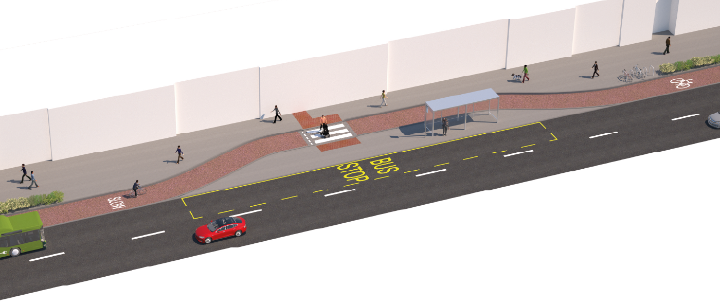
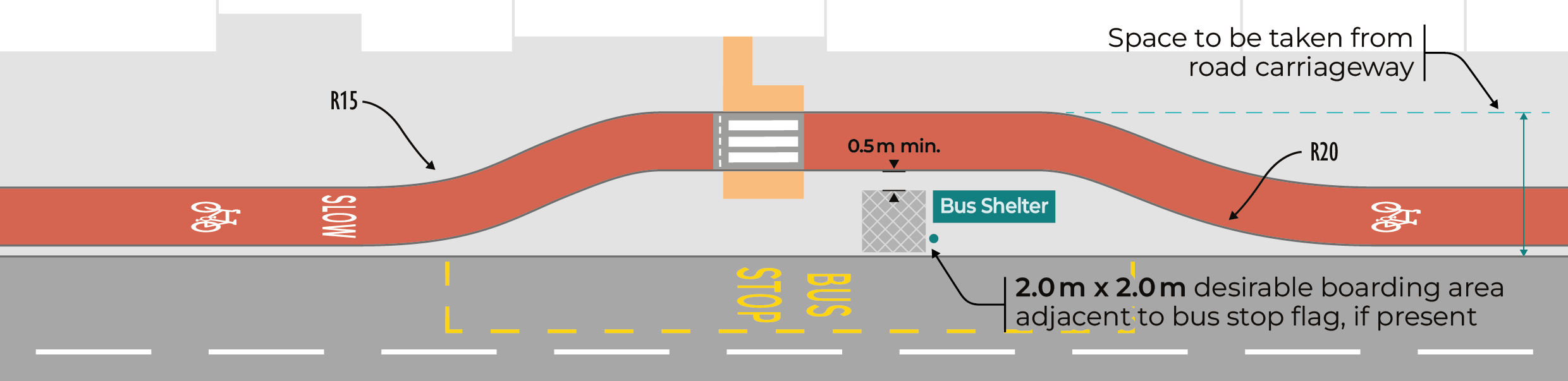
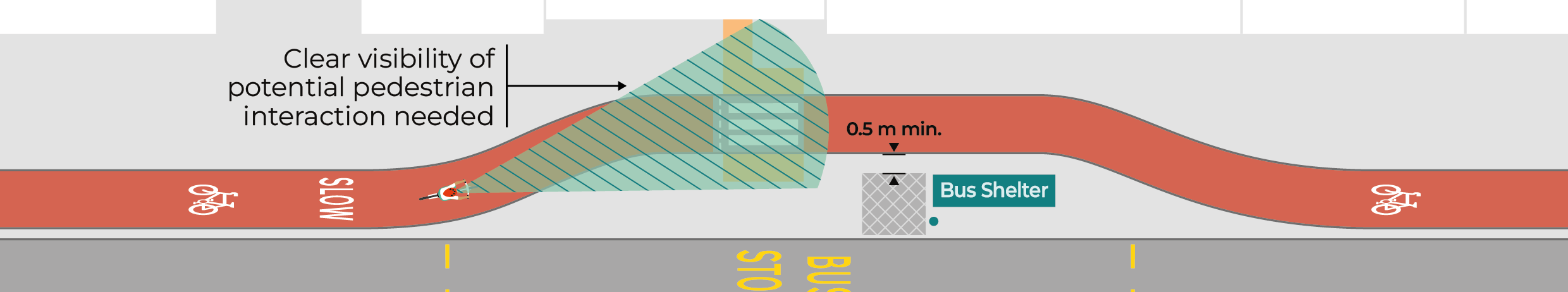
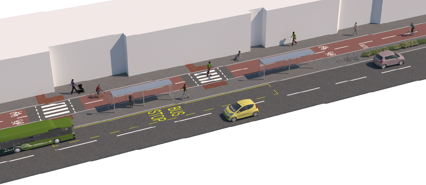
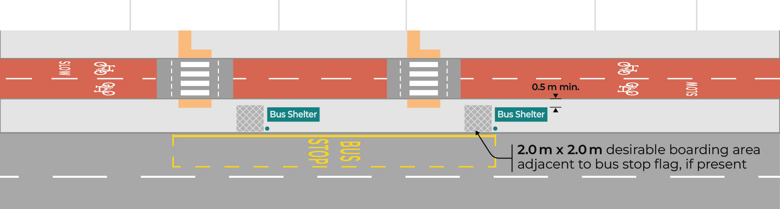
| Clause Number | Description |
|---|---|
| 3.10.1 |
The width of the bus stop island should allow for the width of the shelter, plus at least 0.5 m between the back of the shelter and the cycle track and a suitable distance from the front of the shelter to the road carriageway. Note: Roads for All: Good Practice Guide for Roads recommends the distance from the front of the shelter to the road carriageway to be 1.3 m to allow comfortable circulation space for bus passengers. |
| 3.10.2 | An overall length and width of 2.0 m, clear of any street furniture, should be provided at the bus boarding area to allow wheelchair users to make a 90 degree turn when boarding or alighting the bus. |
| 3.10.3 | A footway width of minimum 2.0 m should be maintained for pedestrians passing the bus stop bypass. |
| 3.10.4 | The cycle track should be at a lower level than the footway and the bus stop island, with a level difference of at least 60 mm. |
| 3.10.5 |
The cycle track width should desirably be maintained at the same width as the approaching cycle track, but should not exceed 2.0 metres for one-way flow, or 3.0 metres for two-way flow. It may be reduced locally in advance of the bus stop bypass if the approaching width is greater. Note: Permitted cycle track widths are limited through the bus stop bypass area to ensure that overtaking is not encouraged. |
| 3.10.6 | Elements with potential to distract cycle users 'attention, including excessive kerb heights, adjacent obstacles at handlebar height and track width variation within the bus stop bypass area should be avoided. Note: Minimising distractions can help to ensure that cycle users are able to focus on potential interactions with pedestrians. |
| 3.10.7 | The maximum crossfall of the bus stop island should be 2.5%. |
| 3.10.8 | Dropped kerbs or raised tables with appropriate tactile paving should be provided to enable accessibility to the bus stop, regardless of the type of crossing provided. |
| 3.10.9 |
Pedestrian crossings should be positioned so that alighting bus passengers can reach a crossing location to their left, as illustrated in Figure 3.22. Note: Appropriate crossing locations may be affected by the position and orientation of the bus shelter. The path between the crossing location and the bus waiting area should be free of street furniture. Note: The requirements for a pedestrian crossing of a cycle track are set out in Chapter 4. |
| 3.10.10 |
The cycle track through the bus stop bypass should incorporate coloured surfacing, and should be visually distinctive from the pedestrian areas. Note: Further advice on coloured surfacing is provided in Section 3.12. |
| 3.10.11 | Bus operators should be consulted, and encouraged to alert passengers when buses are approaching an island bus stop, to be aware of potential cycle movements. |
High cycles speeds through the bus stop bypass should be discouraged. Where cycle speed needs to be controlled, measures should be applied in advance of the pedestrian crossing area, so that these do not distract cycle users’ attention at the crossing location. Horizontal alignment measures such as those illustrated in Figure 3.22 can be an appropriate way of discouraging high speeds. Features such as low-level planting at the start of the island can provide a visual clue to the change in environment.
Transverse bar markings in advance of the bus stop area can emphasise the need for particular concentration by the cycle user as they approach an area where crossing is likely to be more frequent, but should not be used on bends or on uphill slopes. Speed control is particularly important where cycle tracks approach the bus stop on a downhill gradient.
It is essential that the maximum crossfall on the bus stop island is not exceeded, to ensure accessibility. Where a bus boarder kerb is required, the level difference can be accommodated by providing separation between the boarding and crossing location. Alternatively the adjacent footway and cycle track can be locally raised, subject to the constraint imposed by the existing street profile. Note that not all bus operators require a raised bus boarder kerb.
Tactile maps may be added to adjacent bollards or other street furniture to assist blind or partially sighted pedestrians navigate from the crossing to the bus waiting area.
Shared platform boarder
Where space cannot be formed to meet the requirements of a bus stop bypass, a shared platform boarder layout may be considered. This introduces a greater degree of interaction between cycle users and bus passengers, and should only be considered where bus frequency is low.
In this arrangement the dedicated cycle track is truncated, and cycle users are required to enter an area that is shared with pedestrians as they pass the bus stop, as shown in Figure 3.24. This will allow for alternative bus stop door arrangements and for the uncertainty of actual bus stopping positions. The positioning of street furniture including the bus shelter should consider the ability of cycle users to navigate the space.
Two-way cycle tracks at a shared platform boarder will introduce additional interactions and complexity for cycle and bus stop users.
Contrasting surfacing emphasises the mixed use of the space to both pedestrians and cycle users.
| Clause Number | Description |
|---|---|
| 3.10.12 | Cycle tracks should not be continued through the bus boarding or waiting area of a bus stop. |
| 3.10.13 | Bus stops should be designed so that bus passengers are not required to board or alight directly from or into a designated cycle track. |
| 3.10.14 | Shared platform boarder layouts should not be provided where peak bus frequency is greater than 12 buses per hour. |
| 3.10.15 | Where the cycle track is at stepped or carriageway level, it should transition to and from the pedestrian area via a ramp at a maximum of 5% gradient. |
| 3.10.16 | The shared platform boarder area across its full extent should be visually distinctive from both the cycle track and the footpath. |

Cycle lane across inset bus box
Where an inset bus stop is to be maintained, the continuation of a cycle lane across the bus box may be considered. However, this will provide a much lower level of service for cycle users than previous options and consideration should be given to a bus stop bypass within the same space.
This arrangement is less comfortable for cycle users as it places them in conflict with buses entering and exiting the bus stop and between stationary buses and passing motor traffic. This is not the preferred arrangement where space exists for the alternatives introduced previously.
Where used, the cycle lane should be advisory across the length of the bus box to allow bus access and egress, and should transition from a mandatory lane 10 m in advance of the bus stop and back to a mandatory lane 10 m after the bus stop.
Cycle lane across an in-line bus box
An on-road cycle lane may be stopped as it passes through an in-line bus box, but only in the most constrained circumstances.
This arrangement is less comfortable for cycle users as it places them in the traffic lane with other motor traffic, alongside a stationary bus, and forces cycle users to transition into a running lane when buses are stopped. It will also expose cycle users to conflict with buses entering and exiting the bus stop. Benefits are limited to experienced and confident cycle users only.
Where used, the cycle lane should stop at the back of the bus box and recommence immediately after the bus box. Road markings to TSRGD Diagram 1057 (cycle symbol) can be placed in the traffic lane immediately adjacent to the bus box to alert motor vehicle drivers of the potential for cycle users to be in this lane.
On-street parking and loading
A cycle link should not be halted where there is a requirement for on-street parking and kerbside loading.
Removal or relocation of parking can be considered as part of a wider parking review of the area, enabling provision of a more direct and safe cycle link. Careful consideration must be given to disabled parking provision before doing so to ensure that disabled bays are suitably located. Similarly, loading bays may be removed or relocated through consultation with local businesses.
Where the continuation of a cycle link is required to pass on-street parking and loading areas, this can be achieved by a:
- Cycle track on the footway side of on-street parking or loading areas
- Cycle lane being routed along the traffic-side of on-street parking areas.
Alternative cycle links on other routes can be considered where the available width or other local conditions do not make the above options desirable.
Where kerbside loading is to be accommodated alongside cycle tracks, careful consideration should be given to restricting loading times to be outwith periods with the greatest movement of cycle users.
Suitable layouts are described in more detail below. Cycle lanes on the traffic-side of loading areas should be avoided where possible.
Cycle track on footway side of on-street parking
This arrangement provides a cycle track on the footway side of the parking area, which is separated from the parking area by a strip of appropriate width. The strip is formed of a kerbed upstand where the track is at stepped level, or formed by light segregation or coloured surfacing for tracks at carriageway level.
This is the preferred arrangement for cycle users passing a parking area as it avoids placing them between parked vehicles and moving motor traffic, and will usually be more direct. A typical layout is shown in Figure 3.25. In locations where a cycle lane runs immediately adjacent to the road, consideration should be given to transitioning this to a cycle track in advance of the parking to facilitate this layout.
The following issues need particular consideration:
- User awareness – cycle users and motor vehicle users need to be fully aware of each other’s presence. A suitable buffer between the parking area and coloured surfacing of the cycle track will assist with this, as shown in Figure 3.25. Parking areas should stop in advance of the approach to junctions, to provide motor vehicle drivers with good visibility of cycle users before any turning movements at the junction.
- Opening doors – user awareness is paramount where motor vehicle users open their doors. Good visibility of approaching cycle users will assist with this, as will measures to encourage cycle users to slow down. If cycle users are approaching the area downhill and at high speed, it will be more difficult to take corrective action to avoid conflict, and alternative measures should be considered.
- Access to footway – where designated disabled parking spaces are provided, or the parking serves amenities such as doctors’ surgeries, an alternative arrangement that allows disabled vehicle users to exit directly onto the footway may be preferable. This is set out in the following ‘cycle lane on traffic side of on-street parking’ layout.
- Level differences – care is needed when providing carriageway level tracks to ensure that the separation between the parking area and the cycle track does not create a trip hazard. Where kerbed upstands are provided, dropped kerbs should be provided at each end of the parking row to allow footway access
- Street furniture – no street furniture should be placed between the cycle track and the parking area.

| Clause Number | Description |
|---|---|
| 3.11.1 |
Cycle tracks on the footway side of on-street parking should be one-way. Note: Two-way cycle tracks at parking areas will introduce additional interactions for those exiting vehicles and potential disorientation for some users. |
| 3.11.2 | The width of the cycle track and the footway across the length of parking should be in accordance with Section 3.4. |
| 3.11.3 |
The cycle track should be separated from the parking area by a strip of desirable minimum width 1.0 m, which should be increased to 2.0 m alongside disabled parking bays. In constrained situations this may be reduced to an absolute minimum width of 0.5 m. Note: Where designated electric vehicle spaces are provided, the kerbed island between the cycle track and parking should be sufficiently wide to accommodate electric vehicle charging units without any intrusion onto the cycle track. |
Cycle lane on traffic side of on-street parking
In locations where a cycle lane runs immediately adjacent to the road, the cycle lane may be continued on the traffic side of the parking area. This arrangement is less favourable to cycle users as it places them between parked vehicles and moving motor traffic, and will usually be less direct. Options to remove parking that obstructs a more direct cycle route should be considered first.
This may be considered as an alternative if the interaction between cycle users and motor vehicle users exiting their vehicle onto a cycle track cannot be resolved, particularly for the needs of disabled vehicle users. In limited situations, consideration may be given to transitioning a cycle track to pass the parking area for this purpose. However, alternative methods should be explored.
| Clause Number | Description |
|---|---|
| 3.11.4 | The cycle lane should be advisory across the length of parking. |
| 3.11.5 | The transition to a mandatory cycle lane (if required) should occur at the limits of the parking bays. |
| 3.11.6 | The cycle lane should be separated from the parking area by a strip of minimum width 1.0 m. |
| 3.11.7 | SLOW markings may be used to alert drivers to the potential hazard of the cycle lane bend out. |
| 3.11.8 | Where gaps of less than 30 m exist between zones of parking or loading bays, the cycle lane should not be deflected to return to the kerbside. |

Cycle track bypass of a loading island
This is the preferred layout for cycle users passing a loading area as it reduces interaction with loading activities. The layout is similar to the bus stop bypass, as it diverts the cycle track around the back of the loading area.
| Clause Number | Description |
|---|---|
| 3.11.9 |
Cycle tracks on the kerbside of loading areas should be one-way. Note: Two-way cycle tracks at loading areas will introduce additional conflict. |
| 3.11.10 | The loading island should be a desirable minimum width of 2.0 m. In constrained situations it may be reduced to an absolute minimum width of 1.5 m, subject to the buffer requirements set out in Section 3.4. |
| 3.11.11 | The loading island should extend 2.0 m beyond the rear of the marked loading bay to allow loading activity from the rear of the vehicle, with dropped kerbs onto the island provided to facilitate this loading activity. |
| 3.11.12 | If a cycle lane approaches a loading area, it should transition to a cycle track at carriageway level a minimum of 10 m in advance of the loading bay and back to a cycle lane a minimum of 20 m after the loading bay. |
| 3.11.13 | The width of the cycle track and footway along the length of the loading bay should be in accordance with Section 3.4. |
| 3.11.14 | The cycle track should be raised to the same level as the footway and loading island for a length of 5 m to allow loading activities. A raised delineator should be used to denote the change to cycle track at footway level. |
| 3.11.15 | The cycle track surface should be maintained across the loading bay, with loading activities giving way. |

Cycle track at carriageway level with dropped kerbs at loading bay
This arrangement is less attractive for cycle users but may be considered where width is constrained and loading activities are less regular. The narrower width provided between the loading area and the cycle track increases the potential for interaction between cycle users and loading activities. Loading activities are expected to give way to cycle users.
| Clause Number | Description |
|---|---|
| 3.11.16 |
Cycle tracks on the kerbside of loading areas should be one-way. Note: Two-way cycle tracks at loading areas will introduce additional conflict. |
| 3.11.17 | The width of the cycle track across the length of the loading bay should be in accordance with Section 3.4. |
| 3.11.18 | The loading island should be a desirable minimum width of 1.0 m. In constrained situations it may be reduced to an absolute minimum width of 0.5 m. |
| 3.11.19 | Dropped kerbs within the kerbed island should be provided at lengths of 4.0 m minimum (loading side) and 2.4 m minimum (footway side) to facilitate loading activities. |
| 3.11.20 | The cycle track surface should be maintained as it passes the loading bay. |

Construction of cycle links
Pavement construction
The construction of cycle links is important as cycle users are more vulnerable to changes in surface quality and minor defects than other road users.
Figure 3.29 sets out typical pavement construction details for cycle tracks. Designers should engage early with the overseeing organisation to understand specific local requirements.
For mixed traffic streets, cycle lanes, and where cycle tracks are formed from the existing road carriageway, the pavement construction is likely to exceed these pavement construction requirements.
Designers should also engage with overseeing organisations to understand what local, sustainable, and recycled materials are available that can be specified in design, with options for permeable paving investigated in high flood risk areas.
Maintenance requirements are set out in Section 3.13. Ensuring that these requirements are planned for at the design stage will be critical in constructing a robust and durable cycle link with potential to support circular economy principles.
Cycle friendly gullies are available with tighter mesh grates that allow cycles to cross without the risk of wheels catching in the grate gap. These should be provided wherever possible to improve the comfort and attractiveness of the route and avoid the need for additional width where traditional gullies are provided.
Traditional manholes, gullies and other ironwork should not be placed on the running line of cycle wheels, and cycle tracks should be widened where necessary to remove these from the cycling line. Where this cannot be achieved all ironwork should be reset so that it is flush with the carriageway surface and gratings should be orientated to be at right angles to the direction of cycle flow.

Notes for consideration when choosing pavement construction options:
- DMRB CD 239 can be applied for surfaced routes with asphalt, concrete block or clay pavers, natural stone slabs or setts, pre-cast concrete flags or in-situ concrete, which are subject to pedestrian and/or cycle traffic and some overrun by vehicular traffic.
- Additional depth is required to accommodate any vehicular traffic loading (e.g. maintenance vehicles, private resident vehicles, farm vehicles, leisure vehicles).
- A geotechnical assessment of existing ground conditions should be undertaken to specify the appropriate pavement type. If the formation level (subgrade) test performance is below 2.5% (CBR value), the assessment should include measures for ground enhancements (e.g. additional Class 1A material to mitigate soft ground conditions). For trunk road schemes DMRB CD 239 guidance should be followed.
- The sub-base depth to achieve exclusion depth for frost susceptible material is typically 390 mm (including Type 1 granular material as per CC201 Section 8) and as per DMRB CD 239.
- A vehicle loading assessment is required to provide enhanced pavement specification. For trunk road schemes, DMRB CD 239 guidance should be followed.
- A geotexile layer should be considered beneath the sub-base and laid over the approved formation if the ground conditions are poor. This is strongly recommended under unbound paths, regardless of ground conditions.
- Kerbs should be considered for stability on the edges, as well as enhancing drainage and tie-in sections (particularly if vehicle traffic is present) and be provided in accordance with DMRB CD 239.
- For rural areas and root protection areas the pavement can be altered by providing a combined surface/binder course of 60 mm (including Close Graded Asphalt Concrete as per CC202 Section 19).
- Unbound surfaces rely on friction between small aggregate particles (typically graded down from 6mm in size) to help them ‘bind’ together.
- For root protection areas the depth of Cellular Confinement System (or number of layers) should be assessed considering the load bearing capacity and any vehicular shared use of route. Occasionally, an additional sub-base course should be considered.
- Clauses referenced within this Figure and associated notes relate to the Manual of Contract Documents for Highway Works.
Level of Service Indicators – Cycle Link Surface Construction
In relation to Design Principle – Comfort
- High Level of Service: Cycle route surface is machine laid and smooth, with no defects
- Medium Level of Service: Cycle route surface is hand-laid with frequent joints, or contains some defects
- Low Level of Service: Cycle route surface is unbound or deterioration has led to frequent defects
Kerb upstands
Kerb upstands between cycle tracks and footways should provide a level difference of 60 mm to be detectable by blind and partially sighted users.
Kerbs on either side of a cycle track should be splayed at an angle of 45 degrees to reduce the risk of cycle users striking the kerb with their pedal. Where the width of the cycle track is greater than the desirable minimums set out in Section 3.4, existing steeper upstand kerbs can be considered as an alternative.
Transitions between kerb types should be minimised as these can be complex to construct.
Kerb upstands between the road carriageway and the cycle track (or between the road carriageway and the buffer between it and the cycle track) have less influence on cycle user experience and should be specified based on roads authority requirements.
Buffers may be formed of blocked paving, grass verges or asphalt infill between kerbs.
The demarcation between a cycle track and footway at the same level can be formed using tactile paving or a demarcation kerb. This can be formed using a trapezoidal kerb of up to 20 mm in height in accordance with TSRGD Diagram 1049.1, which will be more effective than a painted delineation strip at separating cycle and pedestrian space.
Coloured surfacing
Consistent and distinct use of coloured surfacing within the surface layer on all dedicated cycle links will help differentiate areas and provide visual cues, which will enhance driver awareness of the potential presence of cycle users and the attractiveness of the route for less confident cycle users.
It will also aid orientation and wayfinding, making links more navigable and user friendly for cycle users and pedestrians, and in particular for those who rely to a greater degree on visual cues, which will be important at all points of pedestrian interaction, including junctions, crossings, bus stops and parking areas. Tonal contrast between areas allocated to pedestrians and cycle users will assist partially sighted pedestrians in navigating these spaces.
| Clause Number | Description |
|---|---|
| 3.12.1 | Red coloured surfacing of cycle lanes and cycle tracks adjacent to the road carriageway, which are separated from pedestrians, is recommended, subject to the factors identified below. |
| 3.12.2 | Coloured surfacing is not recommended for cycle tracks which are shared with pedestrians. |
When deciding how to apply this recommendation, roads authorities should carefully consider the following factors:
- Legibility – the more that a consistent surface colour is applied, the greater the level of understanding and appreciation will be for its purposes from all user groups
- Coherence and attractiveness – clear and visually distinguishable cycle facilities will provide greater confidence to new and less confident cycle users that the network is fully joined-up and encourage them to use these facilities more
- Safety priorities – where cost is a constraint, authorities may choose to focus the application of coloured surfacing to locations where the greatest safety risks lie, such as at junctions and on approach to crossings and areas of kerbside activity (parking, loading and bus stops)
- Maintenance – like-for-like repairs to cycle link surfaces will be important for user comfort for the reasons set out above. The ability to repair and maintain coloured surfacing without creating gaps in the coloured surface will be important
- Economies of scale – whilst the unit cost of applying and maintaining coloured surfacing may be higher than an asphalt road surface, there is potential for these unit costs to decrease with increased application and economies of scale across the country.
Consistent use of red where coloured surfaces are applied to cycle links across Scotland will improve understanding by all users. Options for the provision of coloured surfacing are set out in Table 3.11.
|
Option |
Details |
Advantages |
Disadvantages |
|---|---|---|---|
|
Red asphalt surface |
Coloured asphalt with pigmented binder layer |
|
|
|
Red chips within surface |
Coloured chips added to surface layer mix |
|
|
|
Red screed or overlay surface |
Coloured thermoplastic screed or other overlay surface applied directly over existing asphalt surface |
|
|
Table 3.11: Options for cycle link coloured surfacing
Maintenance
Maintenance of cycle links is critical to ensure user safety, to maintain the attractiveness of the network and to improve the value of the network over the longer term.
Poorly maintained cycle links will deter users from making cycle journeys, particularly new and less confident users, who are critical to meeting government policy targets of increased cycling mode share.
Regular inspections of the network are required to identify immediate hazards, potential future hazards and areas with risk of rapid deterioration.
The inspection frequency of the cycle network should be set in the context of the overall maintenance strategy of the maintaining authority. Inspections should be carried out on foot or by cycle.
Inspections should record and prioritise the correction of the following:
- Debris, including broken glass, litter, spillages, stones, gravel, branches and leaves
- Potholes and other deterioration of the path surface (including gaps of 10 mm or greater, depressions of 20 mm or greater or any ‘steps’ that have been created in the surface)
- Loose or rocking slabs
- Loose, broken or misaligned ironwork, including manholes and drainage covers
- Path edge deterioration
- Local ponding or water build-up of 10 mm depth or greater
- Missing or worn road markings
- Deterioration of screed or coloured surface
- Vegetation overgrowth that impacts the path surface, effective width or visibility
- Vandalism or damage to signs, walls, fences, gates, and cycle parking.
Priority for correction of the issues identified during inspection should be based on firstly rectifying immediate hazards, and secondly planning the rectification of issues that could lead to future hazards. The timescales for rectification should be aligned to the maintenance strategy of the maintaining authority and should be no more than the timescales for rectifying the equivalent hazards on the authority’s road network.
Reporting of maintenance needs by cycle users and other members of the public should be encouraged by the maintaining authority.
The maintenance of the cycle link and its surrounding infrastructure should be fully considered at the design stage. This is particularly important for grass verges and landscaping, to ensure that such facilities can be included in the maintaining authority’s inspection and maintenance strategy to avoid compromising user experience.
The requirements for maintenance vehicle access should also be considered at the design stage, with the width and loading requirements of the link designed to accommodate these vehicles.
Access to all cycle tracks by mechanical road brushers is essential. The geometric requirements provided in Section 3.4 will allow for this, but designers should ensure access for these vehicles by avoiding pinch-points that may restrict their access. Where possible, exceeding the desirable minimum widths set out in this chapter will improve opportunities for maintenance.
Key maintenance considerations at the design stage include:
- Sealed surfaces are more costly to install but provide a more comfortable user experience and require less maintenance overall, thereby reducing the whole-life cost of the link
- Suitable cycle track alignment and drainage design will reduce the potential for ponding, associated deterioration and maintenance of the surface
- Planting and vegetation should be offset from the cycle track to allow for regular maintenance and to avoid overgrowth that will impact on the effective width of the cycle link, forward visibility and the visual inspection of the cycle link and associated structures.
Cycle tracks should be prioritised to at least the same level of gritting and winter maintenance as the road network within the local authority maintenance strategy. Opportunities to regularly improve cycling infrastructure should also be identified and incorporated into the road network maintenance programme.
The extent of maintenance responsibilities for a cycle link should be agreed at the design stage. It may be that different sections of the link fall within the maintenance responsibility of the trunk roads authority, local roads authority or others such as Walk Wheel Cycle Trust, Scottish Canals or private landowners. Where this is the case, the designer should identify the extent of these responsibilities to ensure the link can be consistently and effectively maintained upon completion.
Further guidance on maintenance is available in the UK Road Liaison Group’s Well-Managed Highway Infrastructure: a Code of Practice (2016) and Asset Management Guidance for Footways and Cycleways (2018).