Volume 1, Chapter 5 - Iterative Design Development
Introduction
The DMRB Stage 3 design of the proposed scheme as assessed and reported in this EIAR is the result of approximately 17 months of design development to the Preferred Route Option that was identified at DMRB Stage 2 (refer to Chapter 4 (Alternatives Considered)) and announced in December 2023.
Environmental considerations have influenced the design, with knowledge of these gained through the SEA and EIA process, and from the engineering teams, consultees and Transport Scotland. Through this process, the design has been iteratively updated and improved to reach the final DMRB Stage 3 design.
The design development and refinement undertaken during DMRB Stage 3 is key to the EIA process as it presents an opportunity to avoid or mitigate potential effects through changes to aspects such as road alignment, land requirements, or the type and form of major structures. Changes incorporated into the DMRB Stage 3 design during the design process that avoid or reduce potential environmental impacts are often referred to as embedded mitigation.
The potential impacts and proposed mitigation as reported in this EIAR are those identified following assessment of the final DMRB Stage 3 design of the proposed scheme. As such, the potential effects of earlier design iterations are not described in the EIA chapters. This chapter therefore provides an overview of the iterative design process and sets out the key environmental constraints and considerations that informed the final DMRB Stage 3 design.
Iterative Design Process
Constraints Review
One of the key project tools used to help consider environmental constraints was the Jacobs geographical information systems (GIS) based Track Record®. All relevant environmental datasets, including those provided by statutory consultees and other environmental bodies (refer to Chapter 7 (Consultation and Scoping)) and those gathered through desk-based research and field surveys, were loaded onto an interactive database as ‘layers’. Each environmental GIS dataset layer can be switched on or off to show its extents in relation to emerging proposed scheme design.
Track Record® was accessible to all those working on the project, enabling engineers to undertake preliminary sifting prior to review and input by the environmental team. The datasets were used extensively through the design process to enable quick identification of potential issues to inform design development.
Design Assessment
As part of the design process, the engineering design is subject to continuous development and refinement. Examples of design refinement include revisions made to reflect landowner consultation, modelling or survey results (e.g. traffic movements, flood levels, geotechnical surveys), or adding further technical design detail.
To enable informed and timely input to the design, a programme of ‘design revisions’ was therefore established, culminating with the DMRB Stage 3 Design Fix. These snapshots of the draft design enabled all environmental specialists to review the same proposals and provide feedback to the engineers to inform the ongoing proposed scheme development and develop the DMRB Stage 3 Design Fix for the proposed scheme on which this EIAR is based.
Preliminary Design 1 was developed based on the DMRB Stage 2 Whole Route Option ST2D. This was followed by Interim Design 1 and Interim Design 2, each having been informed by environmental, engineering/technical and consultation input. The fourth and final design revision was the DMRB Stage 3 Design Fix on which this EIAR and the draft Orders are based.
Design revisions typically included refinements to:
- vertical alignment (i.e. altering the road height relative to existing ground);
- horizontal alignment (i.e. altering the precise route of the road);
- structures design (e.g. bridge design including earthworks, side roads, and culvert positioning);
- gradients of earthworks slopes (embankments and cuttings);
- routeing of side roads and access roads;
- positioning and alignment watercourse crossings and culverts; and
- positioning and internal design of SuDS and alignment of pre-earthworks drainage (PED); and
- provisions for walkers, cyclists, wheelers and horse-riders (WCH).
Interdisciplinary Mitigation Workshops
During the development of the design revisions, design changes were proposed by the environment teams to avoid or reduce potential impacts. These change requests included modifications to road alignment, earthworks design, siting of drainage features, measures to reduce flood risk, measures to reduce habitat losses and identification of environmentally sensitive areas to be avoided where practicable. This information was used to inform the development of the subsequent design revision.
Interdisciplinary mitigation workshops were used to enable the environmental specialists and engineering design teams to discuss proposals and influence the ongoing design development.
Stakeholder Input
As explained in Chapter 7 (Consultation and Scoping), the A9 Dualling Environmental Steering Group (ESG) which includes SEPA, NatureScot, Historic Environment Scotland, Perth & Kinross Council and Perth & Kinross Heritage Trust met on a regular basis through DMRB Stages 2 and 3, covering all A9 Dualling projects. In addition to input to environmental mitigation as described in the respective chapters of this EIAR, statutory consultees were able to advise and influence various aspects of the draft DMRB Stage 3 design to avoid or reduce potential impacts on environmental factors, including in relation to the water environment and flood risk (SEPA), landscape and visual (PKC and NatureScot), and cultural heritage assets (HES and PKHT).
In addition, consultation with the Non-Motorised User (NMU) Forum (a group set up to engage and seek views of NMU/WCH stakeholders on specific matters relating to the development of the design) and utilising feedback received from public exhibitions informed the development of designs for WCH users and active travel.
The DMRB Stage 3 design has also been informed by discussions with landowners and the owners of affected properties.
Iterative Design Development
Environmental Review Process
Table 5.1 summarises the iterative design development and review process undertaken during DMRB Stage 3.
|
Design iteration |
Design elements considered |
Environmental input and review |
|
Preliminary Design |
Progression of the DMRB Stage2 Whole Route Option ST2D to DMRB Stage 3 with issue of preliminary design for EIA review |
|
|
Interim Design 1 |
Development of DMRB Stage 3 design cognisant public consultation feedback with design development that included:
|
|
|
Interim Design 2 |
Changes to interim design following consultation feedback and consideration of mitigation:
|
|
|
DMRB Stage 3 Design Fix |
DMRB Stage 3 Design Fix for final EIAR and production of Draft Orders:
|
|
Avoiding and/or Reducing Impact on Designated Areas
The iterative design process was able to avoid or reduce potential impacts on designated areas. These design refinements are described as follows.
The River Tay SAC
The River Tay SAC is designated as a Special Area of Conservation (SAC) under the EU Habitats Directive (European Parliament, 1992), providing protection in relation to otter, Atlantic salmon and lamprey (sea, brook and river). It was identified as a key constraint during design development, with the aim of avoiding or reducing the potential impacts of construction and operation such as habitat loss, changes to the watercourse, and water quality.
Examples of where impacts on the River Tay SAC have been avoided or reduced include:
- design of the River Braan Bridge to reduce habitat loss during construction;
- location of the northern and southern piers of the new southbound A9 River Tay Bridge to site them back from the water’s edge to reduce potential impacts on the aquatic and terrestrial habitat of the River Tay SAC; and
- careful selection of outfall locations for road drainage for SuDS Basin A, SuDS Basin B2, SuDS Basin F, SuDS Basin H and SuDS Basin I (refer to Annex A of Appendix A6.1 and Figure 10.6 Landscape and Ecology Mitigation) to reduce habitat loss and potential impacts on qualifying species of the River Tay SAC.
Following design refinement to minimise the impact on the River Tay SAC, the DMRB Stage 3 design requires approximately 0.47ha of permanent loss of aquatic and terrestrial habitats of the River Tay SAC (refer to Chapter 12 (Biodiversity)). The loss of habitats of the River Tay SAC are considered to represent a practicable minimum, taking into account other constraints and technical/safety considerations such as the need for road infrastructure and safety during construction.
Murthly Castle Garden and Designed Landscape
Murthly Castle Garden and Designed Landscape (GDL) is recorded on the Inventory of Gardens and Designed Landscapes (HES, 2024). The Murthly GDL contains Key Landscape Features (the natural landscape features that influenced the landscape design of Murthly Castle GDL), and Special Features (the design elements including planting, land-forming (for example creating artificial slopes), built structures, open ground and water management that form part of the landscape design), which together make up the Murthly GDL.
The Murthly GDL was identified as a key constraint during the design development, with the aim of avoiding or reducing potential impacts of construction and operation of the proposed scheme such as on Key Landscape Features and Special Features of the Murthly GDL.
Examples of where impacts on the Murthly GDL have been avoided or reduced include the following:
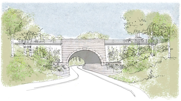
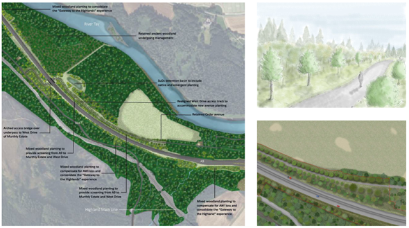
- Design of the Murthly Estate Bridge (refer to Image 6.1) and design and alignment of the Murthly Estate Access Track (refer to Image 6.2) to reduce impacts on formal drives, avenues and paths, including the Western Drive and the Copper Beech Avenue, and provide opportunity for mitigatory planting.
- Location, orientation and design of SuDS Basin A (refer to Annex A of Appendix A6.1 and Figure 10.6) to provide a better landscape fit within the Murthly GDL.
- Development of the Birnam Junction and associated infrastructure to reduce severance of the Murthly GDL.
- Siting of SuDS Basin B2 (refer to Annex A of Appendix A6.1 and Figure 10.6) to provide a better landscape fit within the Murthly GDL.
River Tay (Dunkeld) National Scenic Area
The proposed scheme would affect landscape elements within the River Tay (Dunkeld) National Scenic Area (NSA), resulting from carriageway widening and construction of earthworks and structures (particularly those associated with proposed grade separated junctions) which would alter landcover and landform and result in loss of woodland along the route.
Embedded mitigation measures adopted include the careful alignment of the proposed scheme to avoid or reduce potential impacts on landscape features, particularly those which contribute to Special Landscape Qualities (SLQs) of the NSA. This has primarily been achieved through online widening of the existing A9 and also the grading out of cuttings and embankments to reflect the local topography, as well as the careful siting of SuDS features.
Specific mitigation measures include woodland planting to integrate the proposed scheme into the landscape. Where planting is specified, native and non-native plant species will be used to re-establish or reinforce landscape character. Whilst there is a focus on planting, mitigation measures will also influence the design of structures such as the River Tay Bridge, and SuDS features. Where exposure of rock cuttings is anticipated, such as at Birnam Junction between ch2000 and ch2400, mitigation includes creating a rugged, naturalistic appearance to reflect the character of the rock and fit with the surrounding landscape.
Reducing Loss of Native and Ancient Woodland
The existing A9 passes through extensive areas of woodland, some of which is identified on NatureScot’s Ancient Woodland Inventory (AWI) and/or identified as native woodland through the Native Woodland Survey for Scotland (NWSS). Woodland designated in the AWI is widespread across the study area, typically being found on the eastern valley slopes and in close proximity to the existing A9. Due to the proximity of woodland to the existing A9, it has not been possible to avoid all woodland loss, however where possible, the design has been modified to avoid or reduce woodland loss.
Examples of areas where woodland loss has been reduced through iterative design include the following:
- SuDS Basin B2 was relocated from Birnam Junction to an agricultural field adjacent to Erigmore Caravan Park which avoids the loss of approximately 0.20ha of native woodland listed on the NWSS and AWI.
- On the A822 (Old Military Road), the A822 Dunkeld Junction Retaining Wall was added, avoiding the loss of approximately 0.10ha of nearly native woodland listed on the NWSS and AWI.
At DMRB Stage 3 Design Fix the loss of AWI habitat is quantified as 29.02ha (refer to Chapter 12 (Biodiversity)).
Design to Reduce Flood Risk
The hydraulic model indicates that without mitigation the proposed scheme would increase peak water levels locally within the River Tay and River Braan floodplains. Mitigation measures to prevent these increases have therefore been considered and are discussed in more detail in the following sections.
Embedded Mitigation
Embedded mitigation measures considered during DMRB Stage 3 are detailed in Table 5.2.
|
Measure |
Flood Risk Benefit |
Incorporation in Proposed Scheme |
|
Relocate scheme outside floodplain |
Would prevent loss of floodplain storage on the River Tay. |
A multi-disciplinary technical study looking at potential alternative routes was undertaken at DMRB Stage 2. Routes that completely removed the proposed scheme from the floodplain were considered less favourable due to greater potential environmental impacts and considerably greater cost. Nevertheless, at DMRB Stage 2, the selection of the design for the Birnam Junction considered floodplain loss with the restricted movement Birnam Junction preferred in-part due to there being no encroachment into the floodplain. |
|
Reduce extent of proposed scheme within floodplain |
Would reduce loss of floodplain storage on the River Tay. |
Embankment slopes within the floodplain have been replaced with retaining walls (such as the River Braan Retaining Wall) or steepened to reduce floodplain loss where this was considered appropriate in liaison with landscape and ecology specialists. Where reasonable alternatives existed, SuDS features have been located outwith the River Tay floodplain. The Sewage Works Access Track near Birnam Junction has also been designed to reduce floodplain loss. |
|
Remove raised elements of SuDS ponds within the flood plain |
Would reduce loss of floodplain storage on the River Tay. |
Raised elements of SuDS ponds have been removed from the functional floodplain for SuDS Basin F and SuDS Basin H. |
|
Design of River Braan Bridge and inclusion of flood relief culverts |
Conveyance of flood water from River Braan to River Tay. |
The design of the River Braan Bridge and the inclusion of 14 flood relief culverts of 3.6m x 1.2m with an invert level of 52.1mAOD between ch4400 and ch4500 maintains conveyance of flood waters from the River Braan to the River Tay and mitigates increase in flood risk at key receptors in Inver. |
Compensatory Flood Storage
Where it has not been possible to prevent the proposed scheme from impacting on the functional floodplain by embedding mitigation within the design, the initial measure considered for standalone mitigation has been the provision of compensatory storage that, in accordance with SEPA guidance, provides ‘the same volume and be at the same level relative to the design flood level as that lost’ (SEPA, 2022). The same SEPA guidance also accepts that ‘there may be exceptions’ and that a ‘robust model’ should be used to demonstrate ‘that there would be no increase in flood risk upstream or downstream of the development’.
There are significant constraints to provision of compensatory storage within the proposed scheme area, including geological, ecological, environmental and land constraints. These have all been taken into account as part of the assessment of mitigation measures and appropriate levels of mitigation have been proposed that reflect these constraints.
The primary aim in mitigation design and assessment has been to achieve a neutral impact on flood risk as a result of the proposed scheme. Where this has been identified as impracticable due to local constraints, prevention of increase in flood risk to sensitive receptors such as buildings and local infrastructure has been prioritised over increases to agricultural and other undeveloped land within the existing floodplain.
As the proposed scheme design has progressed an iterative approach to design of mitigation has been followed. The process for identifying required mitigation has generally been as follows:
- Identify areas of floodplain loss or flood risk change as a result of the proposed scheme.
- Identify longlist of potential mitigation options, including areas of potential level for level compensation.
- Undertake multi-criteria analysis of potential options to create shortlist for more detailed consideration.
- Detailed analysis of shortlisted options, generally including hydraulic modelling.
The assessment of impacts on flood risk is presented in Chapter 19 (Road Drainage and the Water Environment) and in Appendix A19.2 (Flood Risk Assessment). The proposed scheme includes one Compensatory Flood Storage Area at ch4400-ch4700 which provides 31,198m3 of Flood Compensatory Storage.
Drainage Design: SuDS Detention Basin v’s SuDS Retention Pond
The proposed scheme includes nine main drainage catchments and, of these drainage catchments, eight have SuDS basins/ponds. SuDS basins/ponds attenuate runoff from the dual carriageway, via filter drains. The SuDS is designed to treat road runoff pollutants to acceptable levels before it enters watercourses. The construction and footprint of the SuDS features are included as part of the DMRB Stage 3 design of the proposed scheme as an embedded measure to mitigate potential water quality impacts.
During design development, engineering and environmental factors were considered to confirm the design of each SuDS feature, including whether attenuation should be achieved by a dry detention basin or by a wet retention pond. The decision was based on guidance in the Construction Industry Research and Information Association (CIRIA) SuDS Manual (CIRIA, 2015), which sets out the four pillars of SuDS design which are water quantity, water quality, amenity and biodiversity. As such, the following were considered:
- Highways England Water Risk Assessment Tool (HEWRAT) assessment, which shows the attenuation levels of a retention pond are typically higher than a detention basin.
- Size and topography of the catchment area.
- Potential issues with seepage into the structural embankment.
- Integrating the SuDS feature within the surrounding landscape character and topography.
- Any potential to contribute to visual amenity.
Chapter 19 (Road Drainage and the Water Environment) provides the outcomes of the process, while further details of the SuDS design principles to be adopted as part of the detailed design and construction of the proposed scheme are set out in Appendix A10.7 (SuDS Design Principles).
The proposed scheme includes seven SuDS detention basins (SuDS Basins A, B2, D, F, G, H and I) and one retention pond (SuDS Pond B1).
Catchment C1 is attenuated through Geocellular Storage and catchments C2, E and G by Swales.
The raising of the mainline vertical level at Dalguise Junction and changing the fall of the side road to drain towards the eastern side of the mainline has removed the requirement for the Pumping Station that was necessary to pump carriageway runoff from the low point to Basin H. By raising the low point above the outfall level the carriageway runoff now drains as a gravity fed solution to Basin H and from Basin H to the River Tay. Other benefits realised by raising the vertical profile of the main alignment include use of surplus material for fill and reduction in cut throughout the northbound loop.
Dunkeld & Birnam Station
Maintaining access
The proposed scheme enables the station to be retained such that it can continue to operate in its current position. However, there would be change of access with access provided via Station Road to a replacement station car park and connection to the station building and platforms provided by a pedestrian underpass with lift/stairs.
Direct vehicular access would be limited to maintenance and emergency vehicles and provided via the Left-in Left-out Station Maintenance Access and the Network Rail Maintenance Access Track. Vehicular access parking for station users would be provided at the replacement car park.
Design to reduce impacts
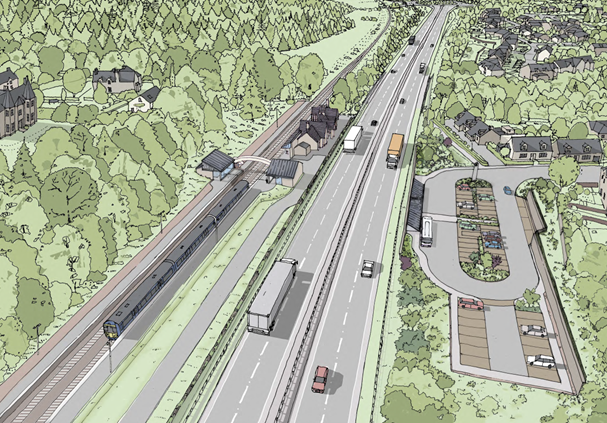
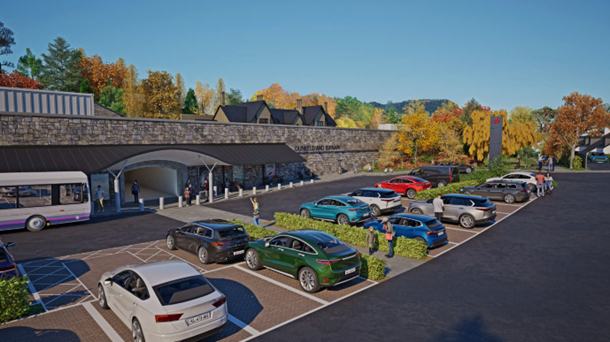
Measures have been developed to re-integrate Dunkeld and Birnam Station with Birnam and reduce the impact on the station. These are detailed in full in Chapter 9 (Cultural Heritage) and Chapter 10 (Landscape). A summary of the main design elements is provided in the sections that follow and illustrations of the design concept are provided in Image 5.3 and Image 5.4.
Station Car Park
High quality paving materials and street furniture to complement Birnam Conservation Area will be used in the carpark. The areas beneath the entrance canopy and the adjacent footway will be paved with whinstone slabs or other paving material of equivalent quality agreed with consultees. Lighting will be designed to complement the street lighting within Birnam Conservation Area.
The car park will be designed to incorporate tree planting areas where practicable and sloped tree and shrub planting areas will extend from the carpark footway to meet the eastern and western sections of the retaining wall.
The car park will incorporate a metal clad totem, circa 5m high incorporating a clock and illuminated British Rail logo, visible from the northern end of Station Road.
Retaining Walls and Station Underpass Entrance Canopy
The retaining wall on the north side of the replacement carpark will be kept to the minimum practicable height and finished to match the retaining wall at the A9 verge (detailed below).
A retaining wall will be constructed between approximate mainline ch3280 and ch3380 with a parapet extending 2m above the A9 verge level clad in masonry in keeping with the masonry of Dunkeld & Birnam Station and will include carving of the words ‘DUNKELD AND BIRNAM’.
The area outside the entrance to the new underpass will incorporate a mono pitched canopy with the pitch angle of the canopy the same as that of the existing station’s platform canopy, except where the front edge of the canopy will be curved up to form a shallow arch at the underpass entrance to match the vaulted form of the underpass entrance. The roof will be supported by stainless steel columns and finished in standing seam zinc.
Pedestrian Underpass
Various iterations of the alignment of the underpass were considered, including an alignment that mirrored that of Station Road. However technical challenges, predominantly in relation to vertical levels and levels within the Dunkeld & Birnam Station replacement car park, have identified a best fit alignment perpendicular to the proposed scheme main alignment, centred in the replacement car park and avoiding impact with the retained Dunkeld & Birnam Station footbridge.
A generous and welcoming underpass will provide access from the replacement station carpark to the station platforms. The underpass to Platform 1 will have a minimum width of 5m and height of 3m, and the continuation to Platform 2 a minimum width of 2.5m and height of 2.5m. The underpass will contain no blind corners.
The ceiling of the underpass will be vaulted/curved, light in colour and with high quality lighting to reduce the sense of enclosure. The underpass walls and floor will be generally clad in tiles.
The underpass will incorporate signage and ticketing facilities as per Scotrail/Network Rail requirements.
Lift/Stair Cores
The lift/stair cores will be provided to Platform 1 and Platform 2 and will have a platform level enclosure, designed to maximise the sunlight/daylight entering the underpass below.
The platform enclosures housing the lift and stairs will have a zinc standing seam roof pitched at approximately 40 degrees with the ridgeline orientated north-south on Platform 1 and east-west on Platform 2. The enclosures will reflect the geometry and scale of the existing station and signal box. Both enclosures will incorporate natural stone, lightweight panels, exposed steelwork and glazed elements where required.
Station Vehicular Access and Parking
Provision of vehicular access to parking spaces will be provided by the replacement station car park. Access for maintenance will be provided by the Left-in Left-out Station Maintenance Access and the Network Rail Maintenance Access Track.
Two car parking spaces will also be provided on Birnam Glen Road, with stepped access to Dunkeld & Birnam Station building.
Provisions for Walkers, Cyclists and Horse-Riders (WCH)
During the design development, the engineering and environmental teams worked to fully consider, maintain and where possible enhance WCH routes affected by the proposed scheme. Embedded mitigation that emerged from this process includes:
- improved access to Dunkeld & Birnam Station for WCH;
- improved WCH provision across the River Tay on the River Tay Bridge
- new path connections;
- path widening; and
Table 5.3 sets out some specific examples of embedded mitigation related to provision for WCH.
|
Location (Path ref.) |
Description of Realignment Proposed |
|
CP01 |
Replacement of at-grade crossing of A9 for Local Path 7 (connecting with Path 3, Path 4 and Path 7a) with Murthly Estate Bridge and realignment of Murthly Estate Access Track. |
|
CP02 |
Replacement of at-grade crossing of Path 23 with provision for WCH incorporated into the design of Birnam Junction. |
|
NCN77, DUNK/142 and DUNK/11 |
Realignment of shared use path between Birnam Junction and Birnam Glen Road. |
|
DUNK/14 |
WCH provision on B867 providing improved connection to DUNK/14 from Perth Road. |
|
DUNK/23, DUNK/137, DUNK/63, DUNK/59 and DUNK/ 10 |
Realignment of paths utilising River Braan Bridge to maintain access to Birnam, Dunkeld, Little Dunkeld and Inver; riverside walks; and to the northbound and southbound bus stops on the A9 main alignment. |
|
NCN77 and DUNK/100 |
Realignment of shared use path and replacement provision on the River Tay Bridge with improved segregation for WCH users. |
Image 5.5 shows the segregation provided for WCH users on the River Tay Bridge.
The assessment of impacts on all travellers is presented in Chapter 17 (Population – Accessibility).
Conclusions
The DMRB Stage 3 design for the proposed scheme is the result of an iterative design development process that avoids or reduces the potential for impacts on the surrounding environment. It has developed and improved the preferred route option that was identified at DMRB Stage 2 (refer to Chapter 4 (Alternatives Considered)) to reach a design that is described in Chapter 6 (The Proposed Scheme) and assessed as part of the DMRB Stage 3 EIAR.
References
National Legislation and EU Directives
- European Parliament (1992). Council Directive 92/43/EEC of 21 May 1992 on the conservation of natural habitats and of wild fauna and flora (Accessed February 2025).
Documents and Reports
- Construction Industry Research and Information Association (2015). CIRIA - The SuDS Manual (C753) (Accessed November 2024).
- Historic Environment Scotland (2024). Murthly Castle (GDL00292) (Accessed November 2024).
- SEPA (2022) Technical Flood Risk Guidance for Stakeholders - SEPA requirements for undertaking a Flood Risk Assessment (Accessed October 2024).